Leakages
This section explains the settings for specifying the leakages in the rolling piston chamber. Leakages can be modeled using the Rolling Piston template as follows.
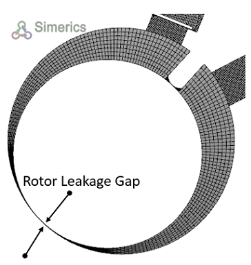
Rotor Leakage GapThis parameter is used to set the physical clearance between rotor and casing (chamber wall) during the creation of the numerical mesh. A non-zero value of the Radial Leakage Gap must be specified during the Rotor Template Mesher in the Geometry Tab of the Properties Panel. Figure 6.679 shows the clearance between rotor and chamber wall.
|
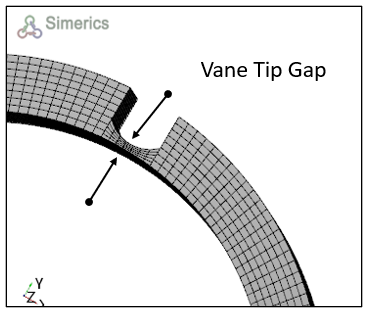
Vane Tip GapThis parameter is used to set the physical tip clearance during the creation of the numerical mesh. A non-zero value of the Vane Tip Gap must be specified during the Rotor Template Mesher in the Geometry Tab of the Properties Panel. Figure 6.680 shows the clearance between rotor and vane tip.
|