|
You are here: Fluid Machinery Templates and Tutorials > Rolling Piston > Rolling Piston Compressor Tutorials > Contours
|
Contours
The most common contours for the rolling piston compressor with valve simulation are the pressure, velocity and temperature contours. To create the contours.
- Click Load Results in the Simulation Panel.
- Select the rollingpiston_withvalve_model_0420.sres result file in the ensuing Load Results dialog box, click Open.
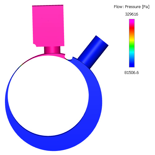
Pressure contours
To obtain the pressure contours on the volumes:
- Select all Volumes in the Geometric Entities Panel.
- Select Pressure from the Variables list under Variable drop-down list in the Results Panel. For variables and legends, refer Post-Processing.
Creating a section
The section is created with the following steps:
- Click Create a Cross-Section
 icon in the Geometric Entities Panel. A new entity Section 01 is created under Derived Surfaces.
 - Select Section 01 under Derived Surfaces and specify the Type as Plane Z and Position as 0.0075 m in the Geometry Tab of Properties Panel.
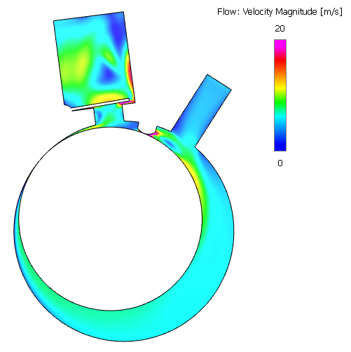
Velocity contours
To obtain the velocity contours on the section:
- Select the Section 01 under Sections in the Geometric Entities Panel.
- Select Velocity Magnitude from the Derived Variables drop-down list under Variable option in the Results Panel.
- Specify Min as 0 m/s and Max as 20 m/s in the Results Panel.
Changes to the display, such as legend, contour color, image sizing and transparency can be made under the View Tab of Properties Panel.
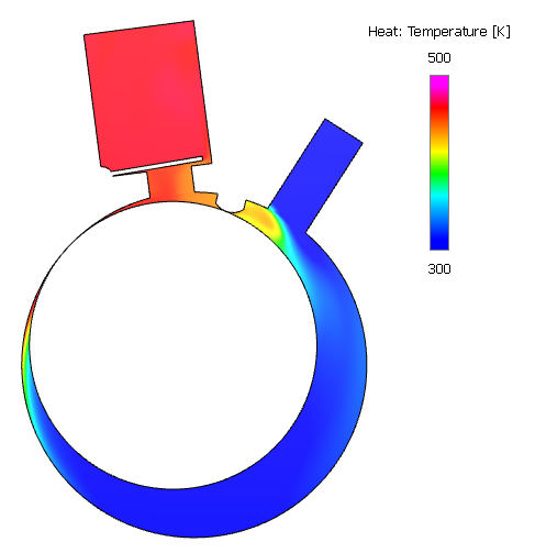
Temperature contours
- Select the Section 01 under Sections in the Geometric Entities Panel.
- Select Temperature from the Variables drop-down list under Variable option in the Results Panel.
- Specify Min as 300 K and Max as 500 K in the Results Panel.
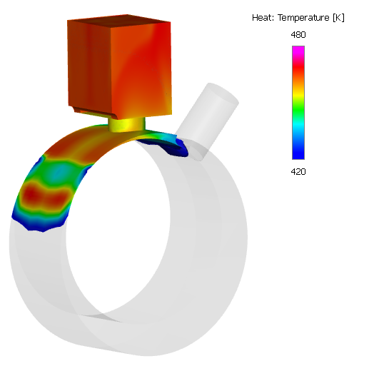
Isosurface of Temperature>420K
An Isosurface is created to show the regions, where temperature is greater than 420 K. These regions are colored with the respective temperature. To create the isosurface:
- Click Create an Isosurface
 icon in the Geometric Entities Panel. An Isosurface 01 is created under Derived Surfaces.
 - Select Isosurface 01 under Derived Surfaces.
- Select Temperature [Heat] from the Variables list in the Isosurface Variable drop-down list in the Geometry Tab of Properties Panel.
- Select Above Value from the Option drop-down list.
- Enter 420 K for Value.
- Select Temperature from the Variables drop-down list under Variable option in the Results Panel.
- Specify Min as 420 K and Max as 480 K in the Results Panel.
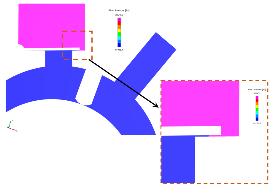
Pressure contours at closed position
The circumferential valve is modelled using the closure model. Figure 6.720 shows the pressure contours at the closed position of the valve.
To obtain the pressure contours as shown in Figure 6.720, the user need to load the result file corresponding to the closed position of the valve also switch to Cell Based View and turn off Smooth Color Map in the Results Panel.