中文 English

Computational domain

This section explains the preparation of surfaces to create the domain. This is done with the operations splitting, combining and renaming of the surfaces.

Split Geometry
  1. Select CAD Surfaces rollingpiston in the Geometric Entities Panel.
  2. Select Split/Combine Geometry or Grid in the Mesh Panel.
  3. Select Split Disconnected from the Operation drop-down list in the Properties Panel, click Split Disconnected. Five new CAD Surfaces are created in the Geometric Entities Panel.
  4. Rename the CAD Surfaces rollingpiston_01, rollingpiston_02, rollingpiston_03, rollingpiston_04 and rollingpiston_05 as rollingpiston, valve, outlet, inlet and port respectively.

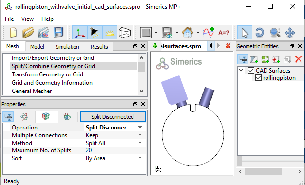
Figure 6.689 - Initial surfaces


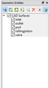
Figure 6.690 - Surfaces after splitting and renaming


Inlet Surfaces
  1. Select the CAD Surfaces entity inlet in the Geometric Entities Panel.
  2. Select Split by Angle from the Operation drop-down list in the Properties Panel.
  3. Enter 75 deg for Angle, click Split by Angle. Three new CAD Surfaces entities inlet_01, inlet_02 and inlet_03 are created in the Geometric Entities Panel.
  4. Rename the CAD Surfaces inlet_01, inlet_02, inlet_03 as inlet_wall, inlet_mgi_rotor and inlet_inlet respectively in the Geometric Entities Panel.


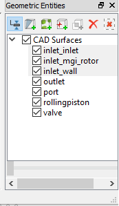
Figure 6.691 - Inlet surfaces
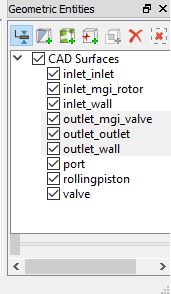
 

Outlet Surfaces
  1. Select the CAD Surfaces entity outlet in the Geometric Entities Panel.
  2. Select Split by Angle from the Operation drop-down list in the Properties Panel.
  3. Enter 75 deg for Angle, click Split by Angle. Seven new CAD Surfaces entities outlet_01 to outlet_07 are created in the Geometric Entities Panel.
  4. Rename the CAD Surfaces outlet_01 and outlet_03 as outlet_mgi_valve and outlet_outlet respectively in the Geometric Entities Panel.
  5. Select the remaining CAD Surfaces entities and select Combine from the Operation drop-down list in the Properties Panel, click Combine.
  6. Rename the combined CAD Surfaces as outlet_wall.


Figure 6.692 - Outlet surfaces


Port Surfaces
  1. Select the CAD Surfaces entity port in the Geometric Entities Panel.
  2. Select Split by Angle from the Operation drop-down list in the Properties Panel.
  3. Enter 75 deg for Angle, click Split by Angle. Three new CAD Surfaces entities port_01 to port_03 are created in the Geometric Entities Panel.
  4. Rename the CAD Surfaces port_01, port_02 and port_03 as port_wall, port _mgi_rotor and port _mgi_valve respectively in the Geometric Entities Panel.


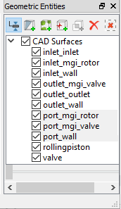
Figure 6.693 - Port surfaces


Rolling Piston Surfaces
  1. Select the CAD Surfaces entity rollingpiston in the Geometric Entities Panel.
  2. Select Split by Angle from the Operation drop-down list in the Properties Panel.
  3. Enter 30 deg for Angle, click Split by Angle. Four new CAD Surfaces entities rollingpiston _01 to rollingpiston _04 are created in the Geometric Entities Panel.
  4. Rename the CAD Surfaces rollingpiston_01 and rollingpiston_04 as rotor_chamber_wall and rotor_vane_tip respectively in the Geometric Entities Panel.
  5. Select the remaining CAD Surfaces entities and select Combine from the Operation drop-down list in the Properties Panel, click Combine.
  6. Rename the combined CAD Surfaces as rotor_vane.


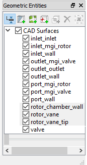
Figure 6.694 - Rolling Piston surfaces


Valve Surfaces
  1. Select the CAD Surfaces entity valve in the Geometric Entities Panel.
  2. Select Split by Angle from the Operation drop-down list in the Properties Panel.
  3. Enter 75 deg for Angle, click Split by Angle. Ten new CAD Surfaces are created in the Geometric Entities Panel.
  4. Rename the CAD Surfaces valve_01, valve_02, valve_03, valve_05 and valve_06 as valve_cylinder_out, valve_mgi_port, valve_end, valve_bottom and valve_top respectively in the Geometric Entities Panel.
  5. Select the CAD Surfaces valve_04. Select Split by Angle from the Operation drop-down list in the Properties Panel.
  6. Enter 50 deg for Angle, click Split by Angle. Two new CAD Surfaces valve_04_01 and valve_04_02 are created in the Geometric Entities Panel. Rename valve_04_02 as valve_cylinder_in.
  7. Select the remaining valve CAD Surfaces and select Combine from the Operation drop-down list in the Properties Panel, click Combine.
  8. Rename the combined CAD Surfaces as valve_valve.


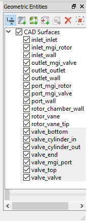
Figure 6.695 - Valve surfaces


Copyright © 2023 Simerics Inc.,