|
You are here: Fluid Machinery Templates and Tutorials > Rolling Piston > Rolling Piston Compressor Tutorials > Building the Mesh
|
Building the Mesh
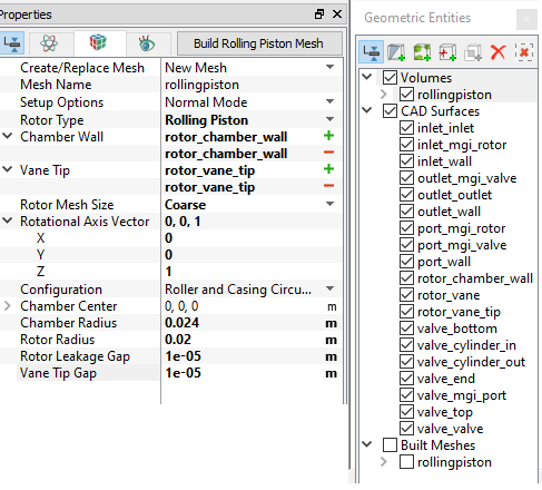
This section describes the step-by-step procedure for preparing the mesh for the rolling piston compressor with valve. The Rolling Piston Template is used to create the rotor chamber mesh and the Valve Template Mesher is used to create the valve mesh.
Valve
|
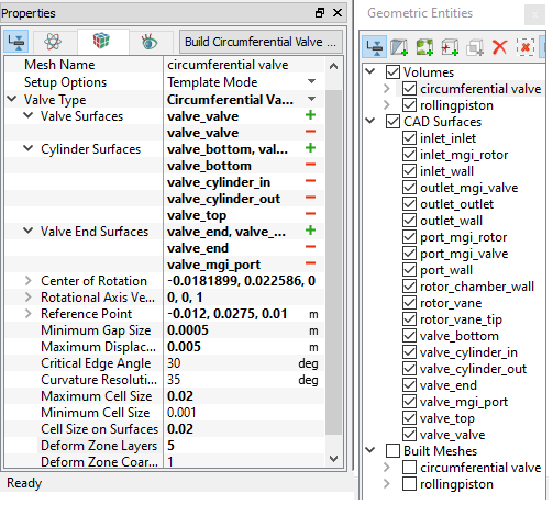
Figure 6.697 - Circumferential valve mesh settings |
Inlet, Outlet and Port
|
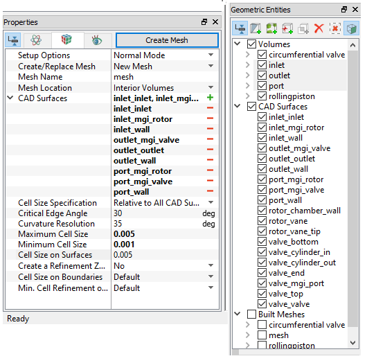
Figure 6.698 - Inlet, outlet and port mesh settings |
The meshes created for the fluid domain are shown below.
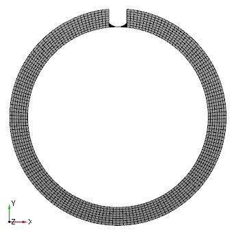
Figure 6.699 - Rolling Piston mesh |
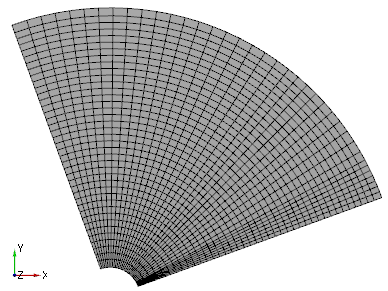
Figure 6.700 - Valve mesh |
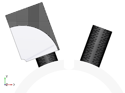
Figure 6.701 - Inlet, outlet and port mesh |
Create interfaces
In this section, the Mismatched Grid Interfaces (MGIs) are generated between boundaries.
The steps to create the MGIs are shown below:
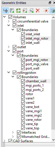
- In Geometric Entities Panel > Volumes > Boundaries, select Boundaries as shown in Table 6.38.
- Click Connect Selected Boundaries via MGI
 icon to create the MGI entities. Refer, Figure 6.702.
A group display of entities can be viewed using the Group Entities by Volumes/Types ![]() icon at Geometric Entities Panel toolbar.
icon at Geometric Entities Panel toolbar.
| Connecting interfaces | Boundaries | Entity |
|---|---|---|
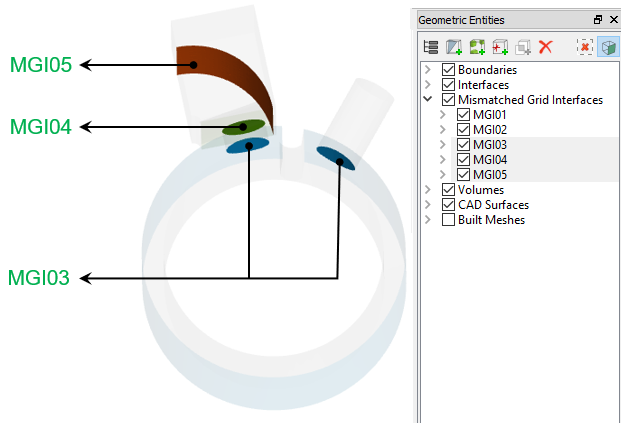
| Inlet, rolling piston chamber and port | inlet_mgi_rotor, chamber_wall and port_mgi_rotor | MGI03 |
| Port and circumferential valve | port_mgi_valve and valve_mgi_port | MGI04 |
| Circumferential valve and outlet | valve_cylinder_out and outlet_mgi_valve | MGI05 |
Table 6.38 - Creating interfaces
The new entities are created under MGI in Volumes, refer Figure 6.703. MGI01 and MGI02 are created automatically by the Rolling Piston Template.
| ´ | Note: If MGIs are created by connecting the wrong boundaries, delete the created MGIs by clicking on Delete Selected Geometric Entity |