中文 English

Defining Physics and Conditions

The physics and conditions are specified as follows:

Adding Modules
  1. Rolling Piston and Circumferential Valve are automatically added to the Model Panel, when these two template meshers are used to generate meshes.
  2. Click Select Modules in the Model Panel. The Physical Model Selection dialog box opens.
  3. Select Turbulence, Heat and Rotation (1 DOF) under Available Modules and click Add.
  4. Click Close to close the Physical Model Selection dialog box.


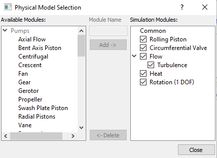
Figure 6.704 - Adding modules

Circumferential Valve Operating Parameters
  1. Select Circumferential Valve in the Model Panel.
  2. Select Rotation (1 DOF) from the Dynamics drop-down list in the Model Tab of Properties Panel, to link the motion of the Circumferential Valve to the Rotation (1 DOF) module.
  3. Enter the parameters for the Valve Configuration as follows:
    • Minimum Gap Size: 5e-05 m
    • Maximum Displacement: 0.005 m
    • Closure Model: Specified Radial Position

      • Radius: 0.0045
      • Center: -0.0092, 0.0259, 0.01
    • Reference Point: -0.012, 0.0275, 0.01
 

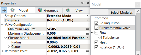
Figure 6.705 - Circumferential Valve Operating parameters


Note:

  1. Closure Model determines whether the flow is fully blocked at the Minimum Gap Size.

  2. The coordinates of the port center are specified as the Center under Closure Model.


Rotation (1 DOF) Operating Parameters
  1. Select Rotation (1 DOF) in the Model Panel.
  2. Select Force Balance in the Motion Type drop-down list.
  3. Enter the parameters for Motion Type as follows:

    • Moment of Inertia: 5e-07 kg-m2

    • Torsion Constant: 2 N-m/rad

    • Torsion Preload Torque: 0.002 N-m
  4. Specify Rotational Axis Vector as 0, 0, 1.
  5. Specify Center of Rotation as -0.0181899, 0.022586, 0.
 

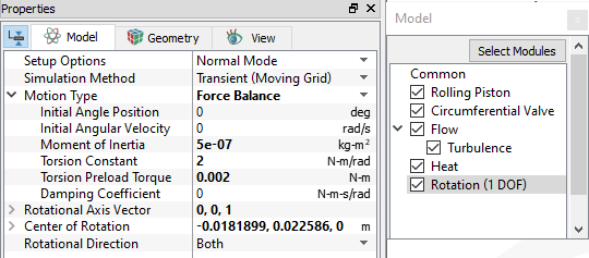
Figure 6.706 - Rotation (1 DOF) - Operating parameters


Rolling Piston Operating Parameters
  1. Select Rolling Piston in the Model Panel.
  2. Enter Number of Revolutions as 3 and Time Steps Per Revolution as 180 for Time Definition in the Model Tab of Properties Panel.
  3. Enter the parameters for the Angular Velocity Definition as follows:

    • Rotational Direction: Clockwise

    • Rotational Speed: 3000 rpm

    • Rotational Axis Vector: 0, 0, 1
 

Note: .

  • The Time Steps Per Revolution is an important parameter and needs to be large enough to achieve a smooth solution.

  • The Number of Revolutions is increased to 4 or 5, so that the results reach a more periodic state.


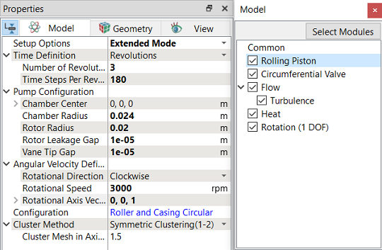
Figure 6.707 - Rolling Piston - Operating parameters

Boundary Conditions

The boundary conditions are preset by the Valve Template Mesher and are specified as follows:

  1. Select the entities under Boundaries in the Geometric Entities Panel, as shown in Table 6.39.
  2. In the Model Tab of Properties Panel, verify the boundary type for the Circumferential Valve drop-down list, as shown in Table 6.39.
Boundaries Circumferential ValveBoundary Type
valve_bottom, valve_cylinder_in, valve_cylinder_out and valve_top Cylinder
valve_end and valve_mgi_port Valve End
valve_valve Valve

Table 6.39 - Valve Boundary type

´ Note:  The rolling piston boundary conditions are assigned to the boundaries of the rollingpiston volume automatically by the Rolling Piston Template.
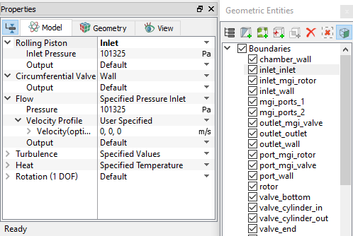
 

Inlet
  1. Select inlet_inlet from the Boundaries list in the Geometric Entities Panel.
  2. Select Inlet from the Rolling Piston drop-down list in the Model Tab of Properties Panel.
  3. Enter Inlet Pressure as 101325 Pa.


Figure 6.708 - Inlet conditions

Outlet
  1. Select outlet_outlet from the Boundaries list in the Geometric Entities Panel.
  2. Select Outlet from the Rolling Piston drop-down list in the Model Tab of Properties Panel.
  3. Enter Outlet Pressure as 300000 Pa.


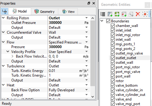
Figure 6.709 - Outlet conditions

Fluid Properties
  1. Select Volumes in the Geometric Entities Panel.
  2. Select Model Tab in the Properties Panel.
  3. Select Ideal Gas for Density under Common.
  4. Select Air for Material under Rolling Piston > Property.
  5. Select Air for Material under Circumferential Valve > Property.
  6. Select the Volumes circumferential valve and outlet in the Geometric Entities Panel.
  7. Specify Value as 410 K under Heat > Initial Condition > Specified Temperature in the Model Tab of the Properties Panel.


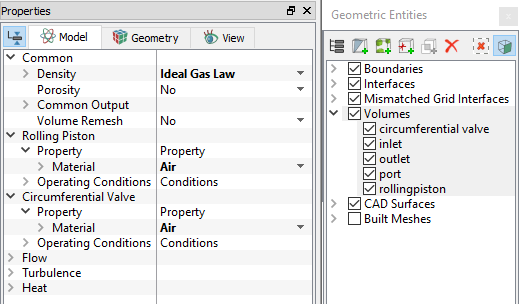
Figure 6.710 - Fluid properties


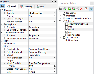
Figure 6.711 - Volume initial temperature


Copyright © 2023 Simerics Inc.,