|
You are here: Fluid Machinery Templates and Tutorials > Rolling Piston > Mesher > Rolling Piston Meshing
|
Rolling Piston Meshing
This section explains the settings for the rolling piston mesh generated using the Rotor Template Mesher. This involves selection of the surfaces, directional characteristics of the mesh and other advanced mesh settings.
The parameters related to Rolling Piston meshing can be accessed by setting the Setup Options to Advanced Mode, as shown in Figure 6.676

Figure 6.676 - Rolling Piston template mesher
Chamber Wall
This is used to assign the chamber wall surface as follows.
- Select the "chamber_wall" surface under CAD Surfaces in the Geometric Entities Panel.
- Click Add Surfaces
 icon to the right of Chamber Wall, or click Select Chamber Wall in the Properties Panel.
|
Note: The Select Chamber Wall operation is the first in the sequence of identifying the parts of the rolling piston. |
Vane Tip
This is used to assign the vane tip surfaces as follows.
- Select the "vane_tip" surface under CAD Surfaces in the Geometric Entities Panel.
- Click Add Surfaces icon to the right of Vane Tip, or click Select Vane Tip in the Properties Panel.
|
Note:
|
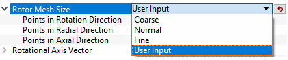
Rotor Mesh SizeThis allows to control the resolution of the mesh created in the rotor chamber as.
|
|
The control parameters associated with User Input (see Figure 6.677) are:
|
Rotational Axis Vector
The direction of the axis of rotation of the rotor in the laboratory reference frame, specified in  coordinates.
ConfigurationIn case of circular casing, such as rolling piston compressor application, Rotor and Casing Circular option helps to model circular chamber. This assumes the roller and chamber wall surfaces are completely circular. In case of non-circular casing, such as Cam application, Rotor and Casing Non-Circular option helps to model non-circular chamber by providing following parameters, under Configuration as shown in Figure 6.678. Rotor Wall: Provide CAD surfaces of rotor wall. Center of Rotation: Provide rotational center of rotor wall. |
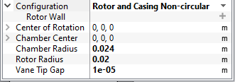
Chamber Radius
This specifies the radius of the chamber in terms of a positive real number in the Chamber Radius option under the Rotor Type. This input under the Rotor Template Mesher can be used in combination with Rotational Axis Vector and Chamber Center to perfect a circular Chamber Wall. If the CAD Surface is within 1% of the cylinder defined by the above parameters, the points on the Chamber Wall boundary created during the meshing operation are adjusted to precisely conform to the cylinder.
- If the cylindrical boundary generated using the Chamber Radius, Rotational Axis Vector and Chamber Center above does not match the corresponding CAD Surface to within 1% of the radius (as in the case of an elliptical housing), the shape of the CAD Surface is used instead.
-
If the above parameters qualify for perfection of the Chamber Wall during meshing, this modification is applied directly to the Chamber Wall boundary and is stored in the .sgrd file.
Rotor Radius
This specifies the radius of the chamber in terms of a positive real number in the Rotor Radius. This input under the Rotor Template Mesher can be used in combination with Rotational Axis Vector and Center of Rotation to perfect a circular Rotor Wall. If the CAD Surface is within 1% of the cylinder defined by the above parameters, the points on the Rotor Wall boundary created during the meshing operation are adjusted to precisely conform to the cylinder.
- If the cylindrical boundary generated using the Rotor Radius, Rotational Axis Vector and Center of Rotation above does not match the corresponding CAD Surface to within 1% of the radius (as in the case of an elliptical housing), the shape of the CAD Surface is used instead.
-
If the above parameters qualify for perfection of the Rotor Wall during meshing, this modification is applied directly to the Rotor Wall boundary and is stored in the .sgrd file.