|
You are here: Fluid Machinery Templates and Tutorials > Rotational Valve > Circumferential Valve Tutorial > Contours
|
Contours
The most common contours for the circumferential valve simulation are the pressure and the velocity contours at sections. The steps to create contours are:
- Click Load Results in the Simulation Panel.
- Select the required result file in the ensuing Load Results dialog box, click Open.
Creating a section
The section is created using the following steps:
- Click Create a Cross-Section
 icon in the Geometric Entities Panel. A new entity Section 01 is created under Derived Surfaces.
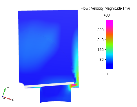
 - Select Section 01 under Derived Surfaces and specify the Type as Plane Z and Position as 0.01 m shown in of the Geometry Tab of Properties Panel.
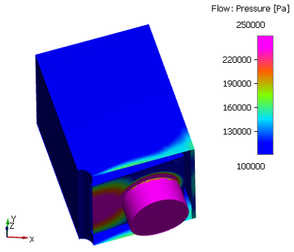
Pressure contours
- Select all boundaries except valve_mgi_inlet under Boundaries in the Geometric Entities Panel.
- Select Pressure from the Variables list under Variable drop-down list in the Results Panel. For variables and legends refer, Post-Processing.
Velocity contours
- Select the Section 01 under Sections in the Geometric Entities Panel.
- Select Velocity Magnitude from the Derived Variables drop-down list under Variable option in the Results Panel.
Changes to the display, such as legend, contour color, image sizing, transparency can be made under the View Tab of Properties Panel.
|
Figure 6.591 - Pressure contours |
Figure 6.592 - Velocity contours |