|
You are here: Fluid Machinery Templates and Tutorials > Rotational Valve > Circumferential Valve Tutorial > Defining Physics and Conditions
|
Defining Physics and Conditions
The physics and conditions are specified as follows.
Adding Modules
|
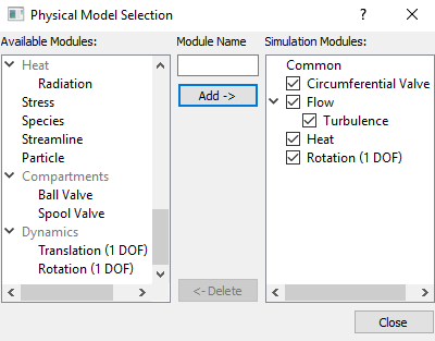
Figure 6.581 - Adding modules |
Circumferential Valve Operating Parameters
|
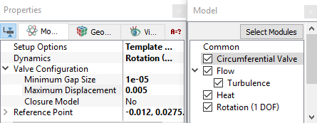
Figure 6.582 - Circumferential valve-Operating parameters |
|
Note:
|
Rotation 1 (DOF) Operating Parameters
|
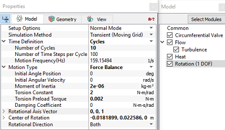
Figure 6.583 - Rotation 1 (DOF) - Operating parameters |
Boundary Conditions
The boundary conditions are preset by the Valve Template Mesher and are specified as follows:
- Select the entities under Boundaries from the Geometric Entities Panel, as shown inTable 6.32.
- In the Model Tab of Properties Panel, verify the boundary type for the Circumferential Valve drop-down list, as shown in Table 6.32.
| Boundaries | Circumferential Boundary Type |
|---|---|
| valve_bot, valve_cylinder_in, valve_cylinder_out, and valve_top | Cylinder |
| valve_end | Valve End |
| valve_mgi_inlet | Valve End |
| valve_valve | Valve |
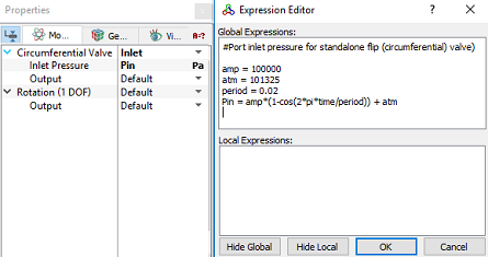
Inlet
amp = 100000 atm = 101325 period = 0.02 Pin = amp*(1-cos(2*pi*time/period)) + atm |
Outlet
|
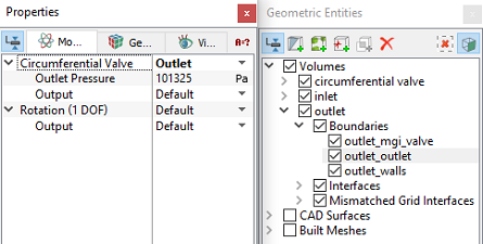
Figure 6.585 - Outlet conditions |
Fluid Properties
Enter the parameters for Operating Conditions as follows.
|
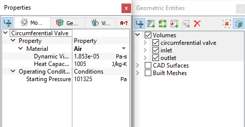
Figure 6.586 - Fluid properties |