6.10.1 Geometry and Domain
The simulation of the circumferential valve requires the understanding of the geometry and the fluid domain enclosed by the surfaces of the valve. The general fluid volume of the circumferential valve and prerequisite steps, before taking into Simerics-MP+ is described as follows:
Prerequisite steps
-
The fluid volume for the circumferential valve consists of: Inlet, outlet ports and deforming volume.
-
For a valve, the fluid volume must be further split into potential expansion/compression zones. For deforming volume, template requires valve, valve end, and cylinder (guiding surface). The guiding surfaces in a circumferential template can be of two types as shown in the figure below. The surfaces cyl_in and cyl_out should be of cylindrical shape with their center on the rotational axis vector and the surfaces cyl_top and cyl_bottom should be planar surfaces as shown in Figure 6.560.
-
While extracting the fluid volume, ensure the position of the valve is between the valve end surfaces.
|
Figure 6.559 - Valve-cyl_top and cyl_bottom |
|


Fluid Domain
The fluid volume in a circumferential valve is defined by CAD Surfaces which enclose them. The circumferential valve primarily consists of the following parts/ volumes : Inlet, Valve, Outlet and Valve Cylinder as shown in Figure 6.561.
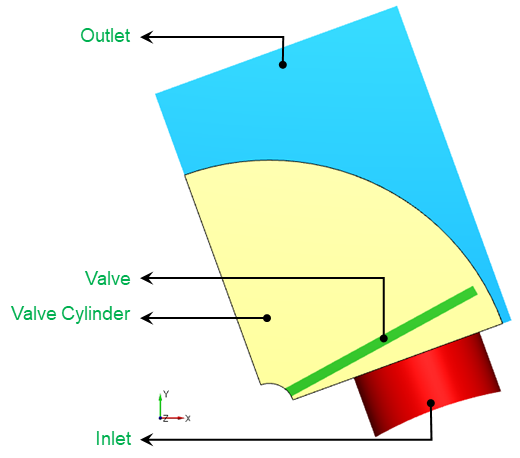
Inlet: The fluid enters the domain through the Inlet boundary. Pressure boundary condition is generally specified at the Inlet, while the other surfaces of the inlet volume are treated as walls.
Valve: The fluid volume which deforms based on the valve motion.
Outlet: The fluid exits the domain through the outlet boundary. Pressure boundary condition is generally specified at the outlet, while the other surfaces of the outlet volume are treated as walls.
For an example of the Circumferential Valve simulation, see Circumferential Valve Tutorial.