6.14.2 Scroll Compressor Mesher
This section explains the settings available in the Scroll template, to generate the dynamic mesh for the rotor. The template enables the creation of mesh with appropriate quality and minimal user effort. The leakages in the crescent pump can also be defined and controlled while meshing. The mesh related settings are accessed as follows:
Mesh Panel > Rotor Template Mesher
The following mesh related settings are available in the Geometry Tab of Properties Panel as shown in Figure 6.785 and Figure 6.786
Create/Replace Mesh: Allows the user to select one of the following:
-
New Mesh: To create a new mesh.
-
Store Build Mesh: To store the mesh settings without generating any mesh.
-
Replace: scroll: To replace the existing mesh with new mesh settings.
Mesh Name: Allows the user to name the mesh prior to mesh creation. This option is available when New Mesh or Store Build Mesh is selected under Create/Replace Mesh.
Setup Options: Allows the user to create the mesh using one of the following modes:
- Normal Mode: This mode provides standard access to the basic parameters to create the mesh.
- Advanced Mode: This mode provides full access to all the meshing parameters to create the mesh.
Rotor Type: Select Scroll from the drop-down list.
|
|


The available parameters related to this template can be accessed by setting the Setup Options as Advanced Mode, as shown in Figure 6.786.
Rotor
This is used to assign the rotor of the scroll as follows:
- Select the rotor surface under CAD Surfaces in Geometric Entities Panel.
- Click Add Surfaces
 icon to the right of Rotor or click Select Rotor in the Properties Panel.
Stator
This is used to assign the stator of the scroll as follows:
- Select the stator surface under CAD Surfaces in Geometric Entities Panel.
- Click Add Surfaces icon to the right of Stator or click Select Stator in the Properties Panel.
Stator End
This parameter is used to identify the stator end surfaces of the scroll compressor as follows (surface for selection is shown in Figure 6.787):
- Select stator end surface under CAD Surfaces in Geometric Entities Panel.
- Click Add Surfaces icon to the right of Stator End or click Select Stator End in the Properties Panel.

Figure 6.787 - Stator end surface
|
Note: The boundary conditions are automatically set by the template for the assigned surfaces. |
Rotor Mesh SizeThis allows to control the resolution of the mesh created in the scroll rotor as:
|
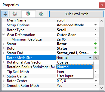

Figure 6.789 - Rotor mesh size-Scroll: Coarse, Fine and Normal
User Input
The control parameters associated with User Input (see Figure 6.788) are:
- Points in Rotational Direction: Corresponds to the number of cell nodes in the rotational direction along one single 360 degree revolution of the rotor (orbiting scroll). The total number of control cells for the whole rotor is dependent on the design of the rotor.
- Points in Radial Direction: Corresponds to the number of cell nodes in the radial direction from the center to the edge of the compression chamber. The number of control cells in this direction is (Points in Radial Direction – 1).
- Points in Axial Direction: Corresponds to the number of cell nodes in the axial direction from the bottom to the top of the compression chamber. The number of control cells in this direction is (Points in Axial Direction – 1).

Figure 6.790 - User input-Scroll
Rotational Axis Vector
The direction of the axis of rotation of the scroll rotor in the laboratory reference frame, in  coordinates.

Figure 6.791 - Rotational axis vector
Rotation Radius Shrinkage (%)
This enables to shrink or enlarge the radius of the rotor relative to the rotor center in terms of percentage. This is used primarily to avoid volume boundary intersections between the stator and rotor surfaces during rotation or to provide the correct known clearances between the two. This parameter is necessary to provide very accurate coordinates for good rotational performance.

Figure 6.792 - Scroll shrinkage (%)
Rotor Center: This specifies the center of the rotor in  coordinates.
Stator Center: This specifies the center of the stator in  coordinates.
Tip Seal MeshThis provides extra leakage path which affects the performance of scroll compressors. It is added as a Volume based on the parameters defined for Tip Seal Mesh. The seal is assumed to always stay on the outer side. The associated parameters to define tip seal mesh and its position are:
|
Figure 6.793 - Tip Seal Mesh |
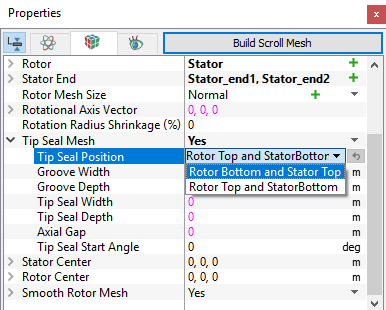

Figure 6.794 - Model with tip seal
Smooth Rotor Mesh
This allows to improve the scroll compressor mesh using a mesh smoothing algorithm, which maximizes cell face orthogonality and optimizes the cell density distribution.

Figure 6.795 - Smooth rotor mesh
- Max Iterations: Specifies the number of iterations, the smoothing algorithm has to run for. The default value is 25, usually optimal for most cases. However, the user can adjust this to capture any desirable mesh characteristics.
- Relaxation (0 < r < 2): Specifies the percentage (i.e. 70% = 0.7 for relaxation value) of the calculated node (cell volume corner point) position displacement increment calculated during the smoothing process. The default value is 1.0.

Figure 6.796 - Relaxation |

Figure 6.797 - Visual representation of relaxation |
Once, the parameters of meshing are defined, click Build Scroll Mesh in the Geometry Tab of the Properties Panel. The Scroll mesh is created and added under the Built Meshes and corresponding Volumes in the Geometric Entities Panel. Also, Scroll module is added to the Model Panel.