中文 English

Computational domain

This section explains the preparation of surfaces to create the domain. This is done with the operations splitting, combining and renaming of the surfaces.

Compressor Surfaces
  1. Select Split/Combine Geometry or Grid in the Mesh Panel.
  2. Select CAD Surfaces scroll in the Geometric Entities Panel.
  3. Select Split Disconnected from the Operation drop-down list in the Properties Panel, click Split Disconnected.
  4. Rename the five new CAD Surfaces scroll_01 as inlet, scroll_02 as scroll_stator, scroll_03 as scroll_rotor, scroll_04 as scrollex and scroll_05 as outlet in the Geometric Entities Panel.

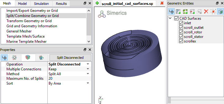
    Figure 6.806 - Split of CAD surfaces


Inlet Surfaces
  1. Select CAD Surfaces inlet in the Geometric Entities Panel.
  2. Select Split by Angle from the Operation drop-down list in the Properties Panel.
  3. Enter 75 deg for Angle, click Split by Angle. Seven new CAD Surfaces are created.
  4. Rename CAD Surfaces inlet_05 as inlet_mgi_scroll and inlet_07 as inlet_inlet in the Geometric Entities Panel.
  5. Select the remaining inlet CAD Surfaces and select Combine from the Operation drop-down list in the Properties Panel, click Combine.
  6. Rename the combined CAD Surfaces as inlet_wall.


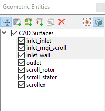
Figure 6.807 - Inlet surfaces

Scroll stator Surfaces
  1. Select CAD Surfaces scroll_stator in the Geometric Entities Panel.
  2. Select Split by Angle from the Operation drop-down list in the Properties Panel.
  3. Enter 75 deg for Angle, click Split by Angle. Two new CAD Surfaces scroll_stator_01 and scroll_stator_02 are created in the Geometric Entities Panel.
  4. Rename CAD Surfaces scroll_stator_01 as scroll_stator and scroll_stator_02 as scroll_stator_end.
´ Note:  There is another segment of the “scroll_stator” surface that will correspond to a fluid-to-fluid interface connecting the scroll volume to the scroll external volume. That surface here could have been isolated using the Split by Angle command, but instead will be isolated later when using the MGI algorithm.


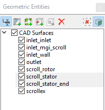
Figure 6.808 - Stator surfaces

Scroll External Surfaces
  1. Select CAD Surfaces scrollex in the Geometric Entities Panel.
  2. Select Split by Angle from the Operation drop-down list in the Properties Panel.
  3. Enter 75 deg for Angle, click Split by Angle. Seven new CAD Surfaces are created in the Geometric Entities Panel.
  4. Rename the CAD Surfaces scrollex_04 as scrollex_mgi_inlet, scrollex_05 as scrollex_mgi_scroll and scrollex_06 as scrollex_mgi_scroll_end.
  5. Select the remaining scrollex CAD Surfaces and select Combine from the Operation drop-down list in the Properties Panel, click Combine.
  6. Rename the combined CAD Surfaces as scrollex_wall.


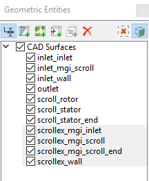
Figure 6.809 - Scroll external surfaces

Outlet Surfaces
  1. Select CAD Surfaces outlet in the Geometric Entities Panel.
  2. Select Split by Angle from the Operation drop-down list in the Properties Panel.
  3. Enter 75 deg for Angle, click Split by Angle. Six new CAD Surfaces are created in the Geometric Entities Panel.
  4. Rename the CAD Surfaces outlet_05 as outlet_outlet and outlet_06 as outlet_mgi_scroll.
  5. Select the remaining outlet CAD Surfaces and select Combine from the Operation drop-down list in the Properties Panel, click Combine.
  6. Rename the combined CAD Surfaces as outlet_wall.


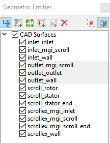
Figure 6.810 - Outlet surfaces


  Note: Splitting of the surfaces can also be done by mouse selection using the Split by Mouse option from the Method drop-down list in the Geometry Tab of Properties Panel.


Copyright © 2023 Simerics Inc.,