中文 English
You are here: Fluid Machinery Templates and Tutorials > Scroll Compressor > Scroll Compressor Tutorial > Defining Physics and Conditions

Defining Physics and Conditions

The physics and conditions are specified as follows.

Adding Modules
  1. Click Select Modules in the Model Panel. The Physical Model Selection dialog box opens.
  2. Scroll is automatically added to the Model Panel by the Rotor Template Mesher.
  3. Select Turbulence under Available Modules and click Add. Similarly add Heat module.
  4. Click Close to close the Physical Model Selection dialog box.


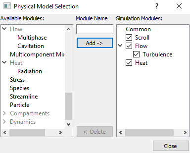
Figure 6.819 - Adding modules

General Operating Parameters
  1. Select Scroll in the Model Panel.
  2. Select Extended Mode from the Setup Options drop-down list in the Model Tab of Properties Panel.
  3. Enter Number of Revolutions and Time Steps Per Revolution as 5 and 120 respectively for the Time Definition.
  4. Verify the Pump Configuration parameters as follows:
    • Stator Center: 0,0,0
    • Rotor Center: -0.0016505829, 0.0014955489, 0
  5. Enter the parameters for the Angular Velocity Definition as follows:
    • Rotational Direction: Clockwise
    • Rotational Speed: 3000 rpm
    • Rotational Axis Vector: 0,0,1
 

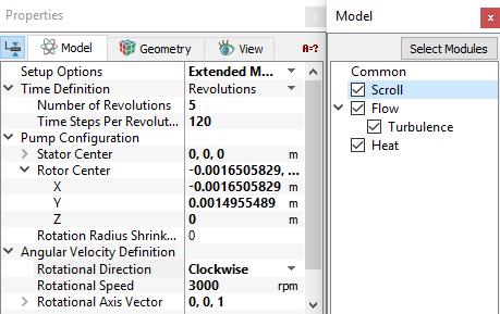
Figure 6.820 - Operating parameters

Heat Module Parameters
  1. Select Heat in the Model Panel.
  2. Enter Temperature Upper Limit as 600 K in the Model Tab of Properties Panel.
  3. Enter Temperature Lower Limit as 100 K.
´ Note:  The limits on temperature (Temperature Upper Limit and Temperature Lower Limit) prevent extreme temperatures during the solution process. They will not affect the final answer, assuming that there would be no temperatures above 600K or below 100K in the actual hardware.


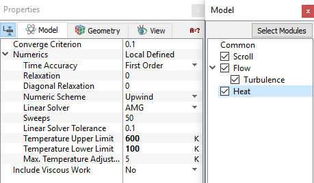
Figure 6.821 - Heat module conditions

Boundary Conditions

The boundary conditions are specified as follows:

Inlet
  1. Select inlet_inlet from the Boundaries list under Volumes in the Geometric Entities Panel.
  2. Select Inlet from the Scroll drop-down list in the Model Tab of Properties Panel.
  3. Enter Inlet Pressure as 101325 Pa.
  4. Enter Temperature as 298 K under Heat.


Figure 6.822 - Inlet conditions

Scroll Rotor
  • The boundary conditions to the rotor_tip, scroll_rotor, scroll_stator and stator_end are automatically assigned by the Scroll module.
  • The instantaneous velocity of the rotor_tip reveal the specific Flow module Boundary Condition. It is computed as part of the Scroll template based on the geometry and operating conditions (e.g. rpm).


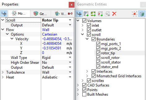
Figure 6.823 - Rotor tip

Outlet
  1. Select  outlet_outlet from the Boundaries list in the Geometric Entities Panel.

  2. Select Outlet from the Scroll drop-down list in the Model Tab of Properties Panel.
  3. Enter Outlet Pressure as 400000 Pa.
  4. Select User Select from the Output drop-down list under Heat.
  5. Select Yes for the Total Enthalpy under Output .


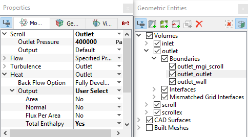
Figure 6.824 - Outlet conditions
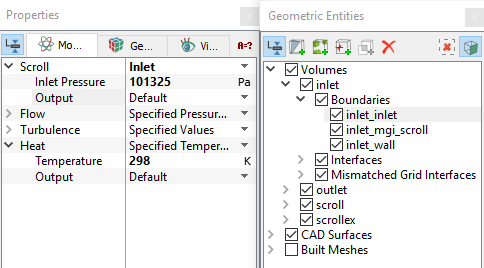
Fluid Properties
  1. Select Volumes in the Geometric Entities Panel.
  2. Select Model Tab in the Properties Panel.
  3. Select Ideal Gas Law from the Density drop-down list under Common.
  4. Enter the parameters for Property list under Scroll as follows:
    • Material: Air
    • Dynamic Viscosity: 1.853e-05 Pa-s


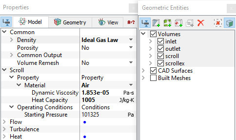
Figure 6.825 - Fluid properties


Copyright © 2023 Simerics Inc.,