|
You are here: Fluid Machinery Templates and Tutorials > Swash Plate Piston Pump > Swash Plate Piston Pump Mesher > Leakages
|
Leakages
This section explains the settings for specifying the leakages in the swash plate piston chamber. Leakages can be modelled using the Swash Plate Piston template as follows.
The parameters related to swash plate piston chamber leakages can be accessed by setting the Setup Options to Advanced Mode.
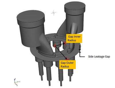
Side Leakage GapThis corresponds to the height of axial gap between the piston pumping chambers and valve plate. Specify a real number for giving the gap height in m. Gap Inner RadiusThis corresponds to the inner radius of the Side Leakage Gap (axial gap). This radius is taken relative to the Rotational Axis Vector. Specify a real number for giving the inner radius in m. Gap Outer RadiusThis corresponds to the outer radius of the Side Leakage Gap (axial gap). This radius is taken relative to the Rotational Axis Vector. Specify a real number for giving the inner radius in m. |
|
Note: A non-zero value of Side Leakage Gap will cause this gap volume to be created under Volumes. A gap with thickness of Side Leakage Gap, is added between the valve plate and cylinder cap and automatically connected to the piston cap volume via MGI. |
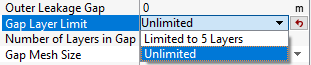
Gap Layer LimitAllows to limit number of mesh layers under Limited to 5 Layers option and allows to add more than 5 mesh layers in gaps under Unlimited option, as shown in Figure 6.409. This option gives user additional control for Number of Layers in Gap, as shown in Figure 6.409. When the Limited to 5 Layers option (the default option) is selected, user can only set up to 5 layers for Number of Layers in Gap. When Unlimited option is selected, user can set any number of layers for Number of Layers in Gap. |
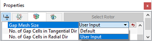
Gap Mesh SizeAllows the user to control the mesh cell size and distribution in the Side Leakage Gap (axial gap). The Gap Mesh Size has the following options:
|
Figure 6.410 - Gap mesh size-Swashplate |
Gap PositionThis allows the user to select the position of Side Leakage Gap (axial gap) between the piston pumping chambers and the valve plate.. The options to specify the Gap Position are as follow:
|
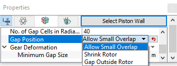
Figure 6.411 - Gap position-Swashplate |