中文 English

Computational domain

This section explains the preparation of surfaces to create the domain. This is done with the operations splitting, combining and renaming of the surfaces.

Pump Surfaces
  1. Select Split/Combine Geometry or Grid in the Mesh Panel.
  2. Select CAD Surfaces pump in the Geometric Entities Panel.
  3. Select Split Disconnected from the Operation drop-down list in the Properties Panel, click Split Disconnected. Eight new CAD Surfaces are created in the Geometric Entities Panel.
  4. Rename the CAD Surfaces pump_01, pump_02 and pump_03 as inlet, outlet and piston respectively.
  5. Select the remaining CAD Surfaces and select Combine from the Operation drop-down list in the Properties Panel.

  6. Click Combine and rename combined CAD Surfaces as vp.

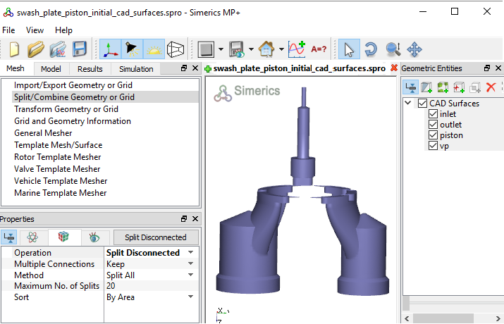
Figure 6.422 - Split of CAD surfaces

Inlet Surfaces
  1. Select CAD Surfaces inlet in the Geometric Entities Panel.
  2. Select Split by Angle from the Operation drop-down list in the Properties Panel.
  3. Enter 75 deg for Angle, click Split by Angle. Three new CAD Surfaces are created in the Geometric Entities Panel.
  4. Rename the CAD Surfaces inlet_01, inlet_02 and inlet_03 as inlet_walls, inlet_inlet and inlet_mgi respectively .


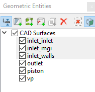
Figure 6.423 - Inlet surfaces

Outlet Surfaces
  1. Select CAD Surfaces outlet in the Geometric Entities Panel.
  2. Select Split by Angle from the Operation drop-down list in the Properties Panel.
  3. Enter 75 deg for Angle, click Split by Angle. Three new CAD Surfaces are created in the Geometric Entities Panel.
  4. Rename the CAD Surfaces outlet_01, outlet_02 and outlet_03 as outlet_walls, outlet_outlet and outlet_mgi respectively .


Figure 6.424 - Outlet surfaces

Piston Surfaces
  1. Select CAD Surfaces piston in the Geometric Entities Panel.
  2. Select Split by Angle from the Operation drop-down list in the Properties Panel.
  3. Enter 75 deg for Angle, click Split by Angle. Eight new CAD Surfaces are created in the Geometric Entities Panel.
  4. Rename the CAD Surfaces piston_01, piston_02, piston_05 and piston_08 as piston_wall, piston_cylinder, piston_mgi and piston_end respectively.
  5. Select the remaining CAD Surfaces and select Combine from the Operation drop-down list in the Properties Panel.
  6. Click Combine and rename the combined CAD Surfaces as piston_cap.


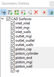
Figure 6.425 - Piston surfaces

Valve Plate Surfaces
  1. Select CAD Surfaces vp in the Geometric Entities Panel.
  2. Select Split by Angle from the Operation drop-down list in the Properties Panel.
  3. Enter 50 deg for Angle, 16 for Maximum No. of Splits and click Split by Angle. Sixteen new CAD Surfaces are created in the Geometric Entities Panel.
  4. Select CAD Surfaces as shown in Table 6.18. Select Combine from the Operation drop-down list in the Properties Panel.
  5. Click Combine and rename with corresponding names as shown in Table 6.18.


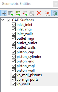
Figure 6.426 - Valve plate surfaces


CAD Surfaces Rename as
vp, vp_01, vp_02, vp_03, vp_04, vp_05 and vp_16 vp_walls
vp_06,vp_07, vp_10, vp_11 and vp_13 vp_mgi_pistons
vp_08, vp_09, vp_12, vp_14 and vp_15 vp_mgi_ports

Table 6.18 - Combine CAD Surfaces


´

Note: 

  1. The geometry in this tutorial does not contain the swash plate. The action of the swash plate is emulated by the Swash Plate Piston module.

  2. Splitting of the surfaces can also be done by mouse selection using the Split by Mouse option from the Method drop-down list in the Geometry Tab of Properties Panel.


Copyright © 2023 Simerics Inc.,