Building the Mesh
This section describes the step-by-step procedure for preparing the mesh for the swash plate piston pump. The Rotor Template Mesher is used to create the piston-cylinder assembly mesh and the General Mesher is used to create the mesh for the inlet, outlet and the valve plate.
Inlet and Outlet Meshes
- Select General Mesher in the Mesh Panel.
- Select CAD Surfaces inlet_inlet, inlet_mgi, inlet_walls, outlet_mgi, outlet_outlet, outlet_walls in the Geometric Entities Panel and click Add Surfaces
 icon for CAD Surfaces in the Properties Panel. icon for CAD Surfaces in the Properties Panel.
- Enter the Maximum Cell Size as 0.01, Minimum Cell Size as 0.001 and Cell Size on Surfaces as 0.005 in the Properties Panel.
- Click Create Mesh. A new mesh mesh is created under Built Meshes in the Geometric Entities Panel.
- The meshed volumes inlet and outlet are generated under Volumes.
|
|
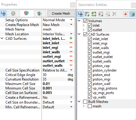
Figure 6.427 - Inlet and Outlet mesh settings
|
Valve plate Mesh
- Select General Mesher in the Mesh Panel.
- Select Advanced Mode for Setup Options drop-down list.
- Select CAD Surfaces vp_mgi_pistons, vp_mgi_ports, vp_walls in the Geometric Entities Panel and click Add Surfaces icon for CAD Surfaces in the Properties Panel.
- Enter Maximum Cell Size as 0.005, Minimum Cell Size as 0.001 and Cell Size on Surfaces as 0.0025 in the Properties Panel.
- Select Combined with Patches for Sub-feature Options drop-down list.
- Select No for Volume Order by Size drop-down list.
- Click Create Mesh. A new mesh vp is created under Built Meshes and vp_1, vp_2, vp_3, vp_4 and vp_5 are generated under Volumes in the Geometric Entities Panel.
- Select Split/Combine Geometry or Grid in the Mesh Panel.
- Select vp_1, vp_2, vp_3, vp_4 and vp_5 under Volumes. Select Combine from the Operation drop-down list in the Properties Panel, click Combine and rename as valve_plate.
- Select the Boundaries as shown in Table 6.19. Select Combine from the Operation drop-down list in the Properties Panel.
- Click Combine and rename with corresponding names as in Table 6.19.
|
|
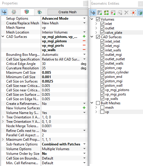
Figure 6.428 - Valve plate mesh settings
|
| vp_walls_1, vp_walls_2, vp_walls_3, vp_walls_4 and vp_walls_5 |
vp_walls
|
| vp_mgi_pistons_1, vp_mgi_pistons_2, vp_mgi_pistons_3, vp_mgi_pistons_4, vp_mgi_pistons_5 |
vp_mgi_pistons
|
| vp_mgi_ ports_1, vp_mgi_ ports_2, vp_mgi_ ports_3, vp_mgi_ ports_4, vp_mgi_ ports_5 |
vp_mgi_ ports
|
Table 6.19 - Combine and rename Boundaries
| ´ |
Note: Two connected Volumes, such as the inlet and valve plate, or valve plate and outlet cannot be meshed together using the General Mesher. |
Piston - cylinder assembly Mesh
- Select Rotor Template Mesher in the Mesh Panel.
- Select Swash Plate Piston from the Rotor Type drop-down list in the Properties Panel
- Select CAD Surfaces piston_end and piston_wall in the Geometric Entities Panel, click Add Surfaces icon for Piston Wall in the Properties Panel.
- Similarly select CAD Surfacepiston_cylinder for Cylinder Wall, piston_cap for Cylinder Cap, and piston_mgi for Cylinder MGI.
-
Enter the parameters as follows.
- Number of Pistons: 9
- Rotational Axis Vector: 0,0,1
- Swash Plate Center: 0,0,-0.2
- Maximum Cell Size: 0.01
- Minimum Cell Size: 0.001
- Cell Size on Surfaces: 0.005
- Click Build Swash Plate Piston Mesh. The new mesh piston is created under Built Meshes in the Geometric Entities Panel.
- The meshed volume piston is generated under Volumes.
|
|
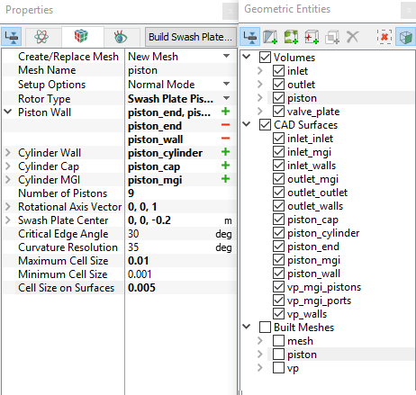
Figure 6.429 - Piston - cylinder mesh settings
|
| |
Note:
- The geometry contains only one piston. The mesh for all the pistons specified under Number of Pistons is automatically generated by the Rotor Template Mesher.
- The imported geometry does not include any leakage gap by default. The parameters for the gaps can be adjusted by selecting Advanced Mode under Setup Options in the Properties Panel.
|
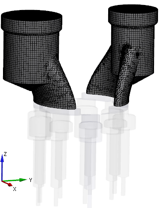
Figure 6.430 - Inlet and Outlet mesh
|
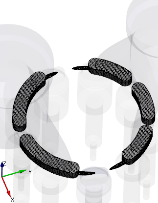
Figure 6.431 - Valve plate mesh
|
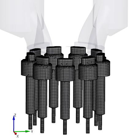
Figure 6.432 - Piston-cylinder assembly mesh
|
Create interfaces
In this section, the Mismatched Grid Interfaces (MGIs) are generated between Boundaries.
The steps to create the MGIs are shown below :
- Geometric Entities Panel > Volumes > Boundaries, elect Boundaries as shown in Table 6.20.
-
Click Connect Selected Boundaries via MGI  icon to create the MGI entities (see, Figure 6.433).
A group display of entities can be viewed using the Group Entities by Volumes/Types  icon at Geometric Entities Panel toolbar.
| Ports and valve plate |
inlet_mgi, outlet_mgi and vp_mgi_ports |
MGI01 |
| Pistons and valve plate |
piston_mgi and vp_mgi_pistons |
MGI02 |
Table 6.20 - Creating interfaces
The new entities are created under MGI in Volumes (see, Figure 6.434).
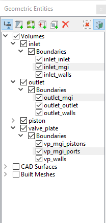
Figure 6.433 - Connecting interfaces
|
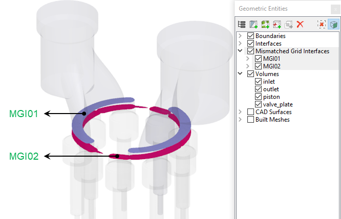
Figure 6.434 - Created interfaces
|
| |
Note: If MGIs are created by connecting the wrong boundaries, delete the created MGIs by clicking on Delete Selected Geometric Entity  icon and recreate the MGIs. icon and recreate the MGIs.
|