|
You are here: Fluid Machinery Templates and Tutorials > Translational Valve > Spool Valve Tutorial > Computational domain
|
Computational domain
This section explains the preparation of surfaces to create the domain. This is done with the operations splitting, combining and renaming of the surfaces. The imported geometry consists of multiple separated fluid volumes as shown in Table 6.26
| CAD Surfaces | Description |
|---|---|
| port | High and low pressure ports |
| valve1 | Fluid domain in the high pressure chamber and until the spool valve surface |
| valve2 | Fluid domain in the low pressure chamber |
| solid-casing_half | Solid surface of half the casing |
| solid-spool | Solid surface of the spool valve |
| solid-spring | Solid surface of the spring |
Port surfaces
- Select CAD Surfaces port in the Geometric Entities Panel.
- Select Split/Combine Geometry or Grid in the Mesh Panel.
- Select Split by Angle from the Operation drop-down list in the Properties Panel.
- Enter 75 deg for Angle, click Split by Angle. Six new CAD Surfaces are created in the Geometric Entities Panel.
- Rename port_03, port_04, port_05 and port_06 as port_mgi_valve2, port_mgi_valve1, port_outlet and port_inlet respectively.
- Select CAD Surfaces port_01 and port_02.
- Select Combine from the Operation drop-down list in the Properties Panel, click Combine and rename as port_wall.
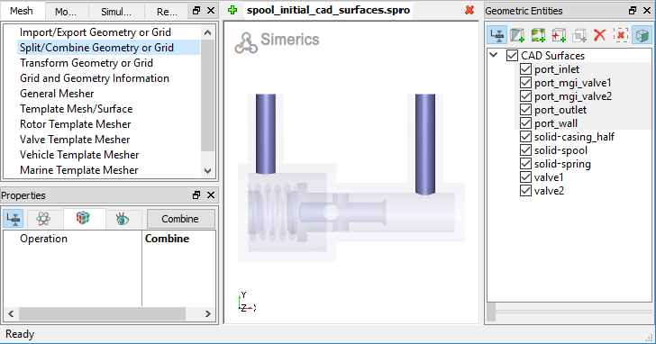
Figure 6.530 - Split of CAD surfaces
Valve1 surfaces
|
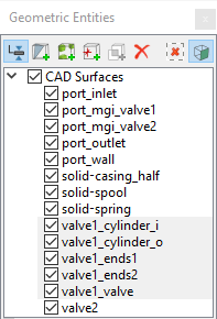
Figure 6.531 - Valve1 surfaces |
Valve2 surfaces
|
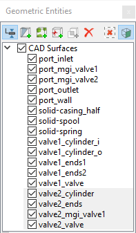
Figure 6.532 - Valve2 surfaces |