|
You are here: Fluid Machinery Templates and Tutorials > Translational Valve > Spool Valve Tutorial > Building the Mesh
|
Building the Mesh
This section describes the step-by-step procedure for preparing the mesh for the spool valve. The Valve Template Mesher is used for creating the spool valve mesh and the General Mesher is used for creating the mesh for the ports, cross channels and high pressure chamber.
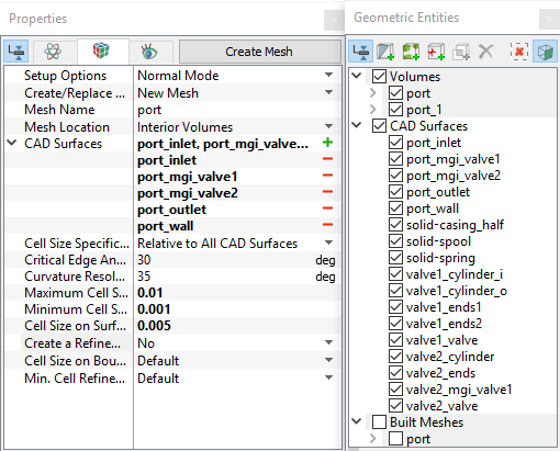
High pressure chamber and cross channels
|
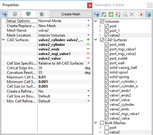
Figure 6.534 - High pressure chamber and cross channels mesh settings |
Spool valve
|
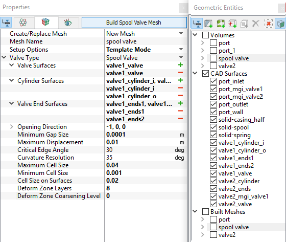
Figure 6.535 - Spool valve mesh settings |
|
Note:
|
The mesh created for the fluid domain is shown below.
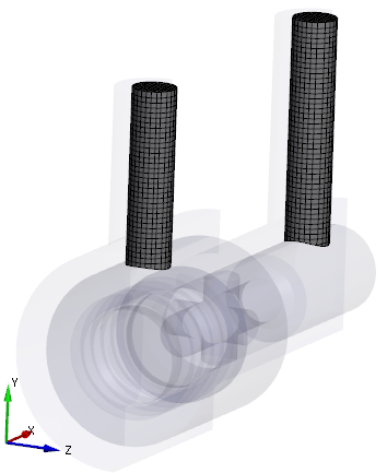
Figure 6.536 - Port mesh |
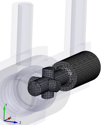
Figure 6.537 - High pressure chamber and cross channels mesh |
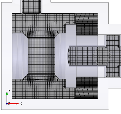
Figure 6.538 - Cross section showing spool valve mesh |
Create interfaces
In this section, the Mismatched Grid Interfaces (MGIs) are generated between boundaries.
The steps to create the MGI is as follows:
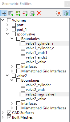
- In Geometric Entities Panel > Volumes > Boundaries, select the Boundaries as shown in Table 6.27.
- Click Connect Selected Boundaries via MGI
 icon upon selecting the required boundaries, to create the MGI entities (see, Figure 6.539).
A group display of entities can be viewed using the Group Entities by Volumes/Types ![]() icon in Geometric Entities Panel toolbar.
icon in Geometric Entities Panel toolbar.
| Connecting interfaces | Boundaries | Entity |
|---|---|---|
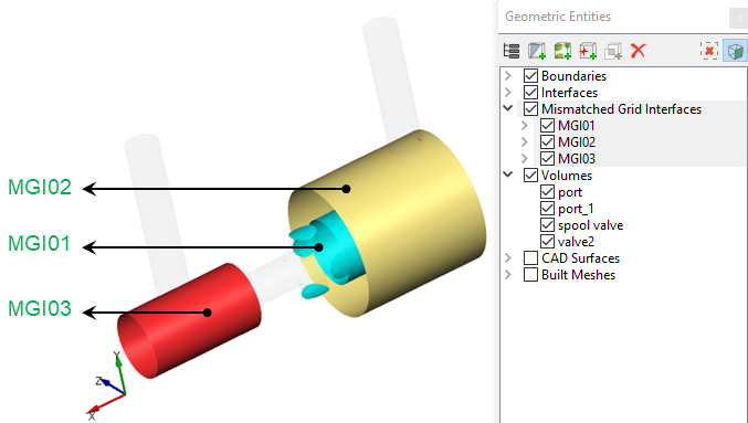
| Cross channels and low pressure chamber cylinder | valve2_mgi_valve1, valve1_cylinder_i | MGI01 |
| Low pressure port and low pressure chamber cylinder | port_mgi_valve1, valve1_cylinder_o | MGI02 |
| High pressure port and high pressure chamber cylinder | port_mgi_valve2, valve2_cylinder | MGI03 |
Table 6.27 - Creating interfaces
The new entities are created under Mismatched Grid Interfaces in Volumes (see, Figure 6.540).
| ´ | Note: If MGIs are created by connecting the wrong boundaries, delete the created MGIs by clicking Delete Selected Geometric Entity |