Defining Physics and Conditions
The physics and conditions are specified as follows.
Adding Modules
- Click Select Modules in the Model Panel. The Physical Model Selection dialog box opens.
- Spool Valve is automatically added to the Model Panel by the Valve Template Mesher.
- Select Cavitation and Translation (1 DOF) under Available Modules list and click Add.
-
Click Close to close the Physical Model Selection dialog box.
|
|
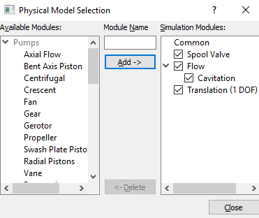
Figure 6.541 - Adding modules
|
Spool Valve Operating Parameters
- Select Spool Valve in the Model Panel.
-
Select Translation (1 DOF) for Dynamics in the Model Tab of Properties Panel, to link the motion of the Spool Valve to the Translation (1 DOF) module.
- Set Minimum Gap Size as 0.0001 and Maximum Displacement as 0.01.
- Select No for the Closure Model drop-down list .
|
|
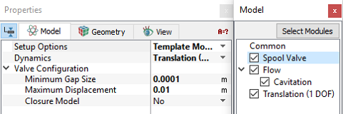
Figure 6.542 - Spool valve operating parameters
|
| ´ |
Note:
- Closure Model determines whether the flow is fully blocked at the Minimum Gap Size.
- The Minimum Gap Size specified in the Valve Template Mesheris larger than that for the actual model, so that the domain has a reasonable cell count.
|
Translation (1 DOF) Operating Parameters
- Select Translation (1 DOF) in the Model Panel.
- Select Advanced Mode for the Setup Options drop-down list in the Model Tab of Properties Panel.
- Enter the parameters for Time Definition as follows.
-
Select Force Balance in the Motion Type drop-down list.
-
Enter the parameters for Motion Type as follows.
- Enter Movement Direction as -1,0,0
| |
Note: The Number of Time Steps per Cycle is an important parameter and must be large enough to achieve a smooth solution. |
|
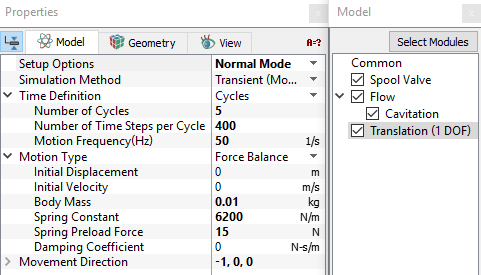
Figure 6.543 - Translation (1 DOF) operating parameters
|
Boundary Conditions
Valve
The boundary conditions for the valve are specified as follows:
- Select the entities under Boundaries from the Geometric Entities Panel, as shown in Table 6.28.
- In the Model Tab of Properties Panel, verify the boundary type for the Spool Valve drop-down list as shown in Table 6.28. The boundary conditions for the valve1 volume generated using the Valve Template Mesher are automatically set by the template. For valve2 boundaries, specify the respective circumferential boundary type as shown in Table 6.28.
| valve1_valve, valve2_valve, valve2_mgi_valve1 |
Valve
|
| valve2_cylinder, valve1_cylinder_i, valve1_cylinder_o |
Cylinder
|
| valve2_ends, valve1_ends1, valve1_ends2 |
Valve End
|
Table 6.28 - Boundary type
Inlet
- Select port_inlet from the Boundaries list in the Geometric Entities Panel.
- Select Inlet from the Spool Valve drop-down list in the Model Tab of Properties Panel.
-
Click Edit Expressions  icon in Inlet Pressure to open the Expression Editor dialog box . icon in Inlet Pressure to open the Expression Editor dialog box .
- Enter the following for Global Expressions (see, Figure 6.544).
p0 = 6e5
dp = 2e5
freq = 50
high_p = dp*sin(2*pi*freq*time)+p0
-
Click OK and enter high_p for the Inlet Pressure.
|
|
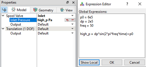
Figure 6.544 - Inlet conditions
|
Outlet
-
Select port_outlet from the Boundaries list under Volumes in the Geometric Entities Panel.
- Select Outlet from the Spool Valve drop-down list in the Model Tab of Properties Panel.
- Enter Outlet Pressure as 101325 Pa.
|
|
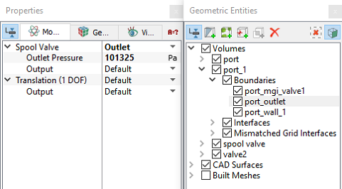
Figure 6.545 - Outlet conditions
|
Fluid Properties
- Select Volumes in the Geometric Entities Panel.
- Select Model Tab in the Properties Panel.
-
Enter the parameters for Property list as follows.
- Material: Oil
- Dynamic Viscosity: 0.007 Pa-s
-
Density: 800 kg/m3
-
Liquid Bulk Modulus(B0): 1.5e+09 Pa
-
Liquid Reference Pressure: 101325 Pa
-
Saturation Pressure: 400 Pa
-
Enter the parameters for Operating Conditions as follows:
|
|
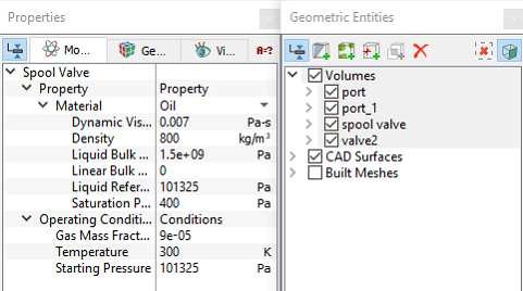
Figure 6.546 - Fluid properties
|