|
You are here: Fluid Machinery Templates and Tutorials > Vane Pump > Vane Pump Tutorials > Computational domain
|
Computational domain
This section explains the preparation of surfaces to create the domain. This is done with the operations splitting, combining and renaming of the surfaces.
Pump Surfaces
- Select CAD Surfaces pump in the Geometric Entities Panel.
- Select Split/Combine Geometry or Grid in the Mesh Panel.
- Select Split Disconnected from the Operation drop-down list in the Properties Panel, click Split Disconnected. Ten new CAD Surfaces are created in the Geometric Entities Panel.
- Rename the CAD Surfaces pump_01, pump_02, pump_03 and pump_04 as rotor_chamber, slider1, rotor and slider2 respectively.
- Select CAD Surfaces pump_05 and pump_06. Select Combine from the Operation drop-down list in the Properties Panel.
- Click Combine and rename as port. Similarly select CAD Surfaces pump_08, and pump_09, click Combine and rename as groove.
- Rename the CAD Surfaces pump_07 and pump_10 as control and release respectively.
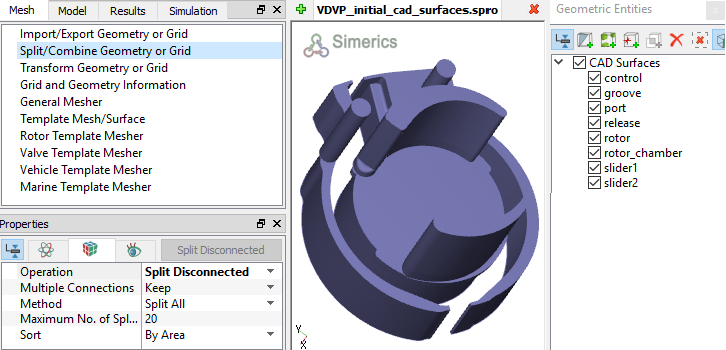
Figure 6.253 - Split of CAD surfaces
Port Surfaces
|
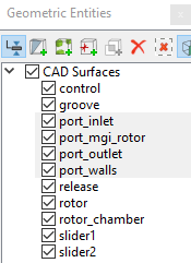
Figure 6.254 - Port surfaces |
Rotor Surfaces
|
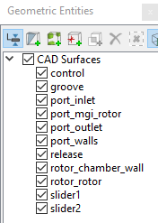
Figure 6.255 - Rotor surfaces
|
| ´ | Note: The surfaces are deleted as they are not needed to create the mesh. |
Release Surfaces
|
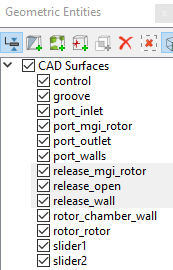
Figure 6.256 - Release surfaces |
Control surfaces
|
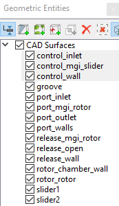
Figure 6.257 - Control surfaces |
|
Groove surfaces
|
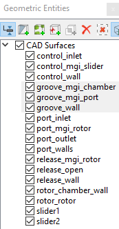
Figure 6.258 - Groove surfaces |
| Note: In addition to the usual surface preparation for vane pump modelling, one needs to prepare the Surfaces/Boundaries for the slide bars. Since the mesh movement of the sliders is modelled using Rotation (1 DOF) module in conjunction with the Circumferential Valve module, the slider Boundaries is divided into the surfaces: Valve, Valve End, and Cylinders |
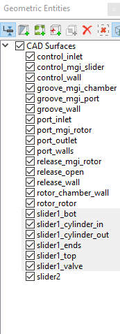
Slider1 surfaces
- Select CAD Surfacesslider1 in the Geometric Entities Panel.
- Select Split by Angle from the Operation drop-down list in the Properties Panel.
- Enter 75 deg for Angle, click Split by Angle. Six new CAD Surfaces slider1_01 to slider1_06 are created in the Geometric Entities Panel.
- Rename slider1_01, slider1_02, slider1_03, slider1_04 and slider1_05 as slider1_ends, slider1_valve, slider1_top, slider1_bot and slider1_cylinder_in respectively.
- Select CAD Surfaces slider1_valve and slider1_06.
- Select Combine from the Operation drop-down list in the Properties Panel, click Combine and rename as slider1_valve.
- Split the CAD Surfaces of the Table 6.6 as follows.
| Note: The Outer Cylinder needs to be split away from the slider1_ends, but this will require small splitting angles. The curved edges make it more difficult to separate surfaces, thus creating the necessity of using a small splitting angle. It is also recommended to limit the Maximum No. of Splits. |
- Geometric Entities Panel > Select the CAD Surfaces > Properties Panel > Select Split by Angle from the Operation drop-down list.
- Enter Angle > Enter Maximum No. of Splits > Click Split by Angle.
| CAD Surfaces | Angle (deg) | Maximum No of Splits |
|---|---|---|
| slider1_ends | 1 | 5 |
| slider1_ends_02 | 0.1 | 2 |
Table 6.6 - Split/Rename Slider1 CAD surfaces
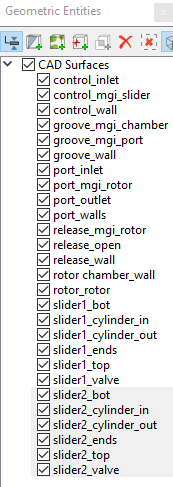
Slider2 surfaces
- Select the CAD Surfaces slider2 in the Geometric Entities Panel.
- Select Split by Angle from the Operation drop-down list in the Properties Panel.
- Enter 75 deg for Angle, click Split by Angle. Six new CAD Surfaces are created in the Geometric Entities Panel.
- Rename slider2_01, slider2_02, slider2_03, slider2_04 and slider2_05 as slider2_ends, slider2_valve, slider2_bot, slider2_top and slider2_cylinder_in respectively.
- Select CAD Surfacesslider2_valve and slider2_06. Select Combine from the Operation drop-down list in the Properties Panel, click Combine and rename as slider2_valve.
-
Select the CAD Surfaces slider2_ends in the Geometric Entities Panel.
- Select Split by Angle from the Operation drop-down list in the Properties Panel.
- Enter 1 deg for Angle and 5 for Maximum No. of Splits, click Split by Angle. Five new CAD Surfaces are created in the Geometric Entities Panel.
- Select CAD Surfaces slider2_ends_03 and rename as slider2_cylinder_out.
- Select the remaining slider2_ends CAD Surfaces. Select Combine from the Operation drop-down list in the Properties Panel, click Combine and rename as slider2_ends refer, Figure 6.260.
| Note: The Outer Cylinder needs to be split away from the slider2_ends, but this will require small splitting angles. The curved edges make it more difficult to separate surfaces, thus creating the necessity of using a small splitting angle. It is also recommended to limit the Maximum No. of Splits. |