Building the Mesh
This section describes the step-by-step procedure for preparing the mesh for the VDVP pump. The Rotor Template Mesher is used to create the chamber mesh and the General Mesher is used for the inlet, outlet, and grooves.
Port Mesh
- Select General Mesher in the Mesh Panel.
- Select CAD Surfaces port_inlet, port_mgi_rotor, port_outlet and port_wall in the Geometric Entities Panel and click Add Surfaces
 icon for CAD Surfaces in the Properties Panel. icon for CAD Surfaces in the Properties Panel.
- Enter Maximum Cell Size as 0.01, Minimum Cell Size as 0.001 and Cell Size on Surfaces as 0.005 in the Properties Panel.
- Click Create Mesh. A new mesh port is created under Built Meshes in the Geometric Entities Panel.
- To refine the interfaces, select port in Built Meshes and port_mgi_rotor from CAD Surfaces. Select User Input from the Cell Size on Boundaries drop-down list and enter 0.0025 for Size in the Properties Panel.
- Click Create Mesh to update port under Built Meshes in the Geometric Entities Panel.
- Select Split/Combine Geometry or Grid in the Mesh Panel and Select port, port_1 under Volumes. Select Combine from the Operation drop-down list in the Properties Panel, click Combine and rename as port.
- Select Boundaries port_walls and port_walls_1, click Combine and rename as port_walls.
- Select Boundaries port_mgi_rotor and port_mgi_rotor_1, click Combine and rename as port_mgi_rotor.
-
The meshed volume port is generated under Volumes.
|
|
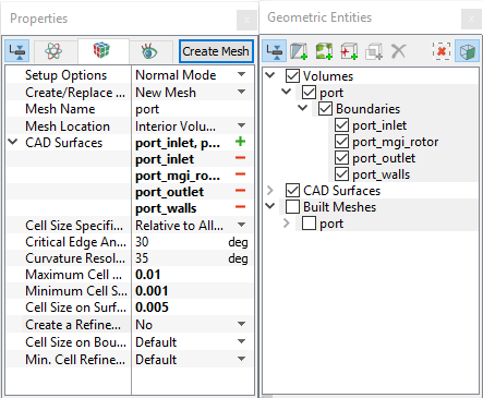
Figure 6.261 - Port mesh settings
|
Rotor Chamber
- Select Rotor Template Mesher in the Mesh Panel.
- Select Vane from the Rotor Type and Variable Displacement from the Design Type drop-down list in the Properties Panel.
- Select CAD Surfaces rotor_rotor in the Geometric Entities Panel, click Add Surfaces icon for Rotor in the Properties Panel. Similarly, select CAD Surfaces rotor_chamber_wall, click Add Surfaces for Chamber Wall.
-
Enter the parameters as follows.
- Click Build Vane Mesh. The new mesh vane is created under Built Meshes in the Geometric Entities Panel.
- The meshed volume vane is generated under Volumes.
|
|

Figure 6.262 - Rotor mesh settings
|
Control and Release Mesh
- Select General Mesher in the Mesh Panel.
- Select the CAD Surfaces control_inlet, control_mgi_slider, control_wall, release_mgi_rotor, release_open and release_wall in the Geometric Entities Panel and click Add Surfaces icon for CAD Surfaces in the Properties Panel.
- Enter Maximum Cell Size to 0.01, Minimum Cell Size to 0.001 and Cell Size on Surfaces to 0.005 in the Properties Panel.
- Click Create Mesh. A new mesh mesh is created under Built Meshes in the Geometric Entities Panel.
- To refine the interfaces, select mesh in Built Meshes and control_mgi_slider, release_mgi_rotor from CAD Surfaces.
- Select User Input from the Cell Size on Boundaries drop-down list, enter 0.0025 for Size in the Properties Panel.
- Click Create Mesh to update mesh under Built Meshes in the Geometric Entities Panel.
- The meshed volumes control and release are generated under Volumes.
|
|
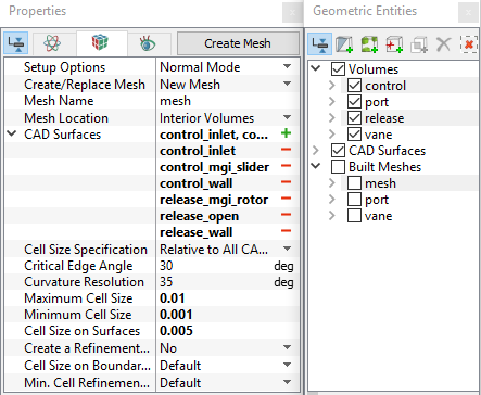
Figure 6.263 - Control and Release mesh settings
|
Slider1 Mesh
- Select Valve Template Mesher in the Mesh Panel.
- Select Circumferential Valve from the Valve Type drop-down list in the Properties Panel.
- Select CAD Surfaces slider1_valve in the Geometric Entities Panel, click Add Surfaces icon for Valve Surfaces in the Properties Panel. Similarly, select CAD Surfaces slider1_top, slider1_bot, slider1_cylinder_in and slider1_cylinder_out and click Add Surfaces for Cylinder Surfaces.
- Select CAD Surfaces slider1_ends, click Add Surfaces for Valve End Surfaces.
-
Enter the parameters as follows.
- Click Build Circumferential Valve Mesh. The new mesh circumferential valve is created under Built Meshes in the Geometric Entities Panel.
-
The meshed volume circumferential valve is generated under Volumes and rename as slider1.
|
|
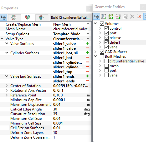
Figure 6.264 - Slider1 mesh settings
|
| ´ |
Note: If sub-features are sharing different parts of the valve i.e. (valve end and valve), then perform the Split/Combine Geometry or Grid operation and connect to the respective boundaries. |
Slider2 Mesh
- Select Valve Template Mesher in the Mesh Panel.
- Select Circumferential Valve from the Valve Type drop-down list in the Properties Panel.
- Select the CAD Surfaces slider2_valve in the Geometric Entities Panel, click Add Surfaces
 icon for Valve Surfaces in the Properties Panel. Similarly, select CAD Surfaces slider2_top, slider2_bot, slider2_cylinder_in and slider2_cylinder_out, click Add Surfaces for Cylinder Surfaces. icon for Valve Surfaces in the Properties Panel. Similarly, select CAD Surfaces slider2_top, slider2_bot, slider2_cylinder_in and slider2_cylinder_out, click Add Surfaces for Cylinder Surfaces.
- Select CAD Surfaces slider2_ends, click Add Surfaces for Valve End Surfaces.
-
Enter the parameters as follows.
- Click Build Circumferential Valve Mesh. The new mesh circumferential valve1 is created under Built Meshes in the Geometric Entities Panel.
-
The meshed volume circumferential valve_1 is generated under Volumes and rename as slider2.
|
|
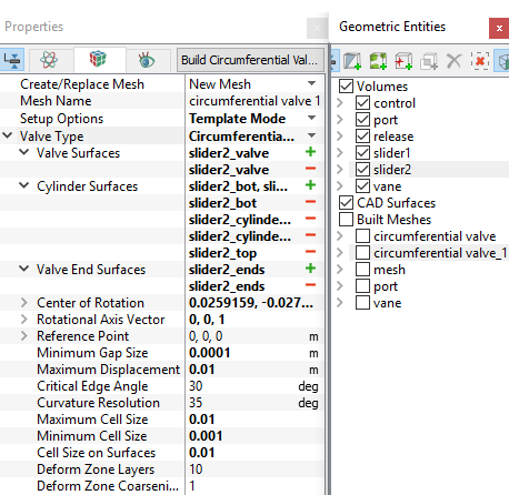
Figure 6.265 - Slider2 mesh settings
|
Groove Mesh
- Select General Mesher in the Mesh Panel.
- Select all groove CAD Surfaces in the Geometric Entities Panel and click Add Surfaces icon for CAD Surfaces in the Properties Panel.
- Enter Maximum Cell Size as 0.01, Minimum Cell Size as 0.001 and Cell Size on Surfaces as 0.005 in the Properties Panel.
- Click Create Mesh. A new mesh groove is created under Built Meshes in the Geometric Entities Panel and meshed volume groove, groove_1 are generated under Volumes.
- To refine interfaces, select groove in Built Meshes and groove_mgi_chamber, groove_mgi_port from CAD Surfaces .
-
Select User Input from Cell Size on Boundaries drop-down list, enter 0.0025 for Size in the Properties Panel.
Click Create Mesh. The mesh groove is updated under Built Meshes in the Geometric Entities Panel.
- Select groove and groove_1 under Volumes. Select Split/Combine Geometry or Grid in the Mesh Panel.
- Select Combine from the Operation drop-down list in the Properties Panel, click Combine and rename as groove.
- Select the Boundaries as shown in Table 6.7. Select Combine from the Operation drop-down list in the Properties Panel.
- Click Combine and rename with corresponding names as in Table 6.7.
|
|
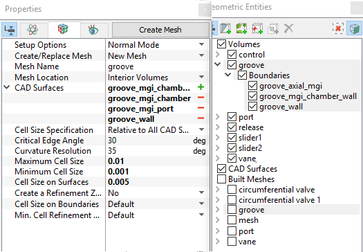
Figure 6.266 - Groove mesh settings
|
| groove_mgi_chamber and groove_mgi_chamber_1 |
groove_mgi_chamber_wall |
| groove_mgi_port and groove_mgi_port_1 |
groove_axial_mgi |
| groove_wall and groove_wall_1 |
groove_wall |
Table 6.7 - Combine and rename Boundaries
The mesh created for the fluid domain is shown below.
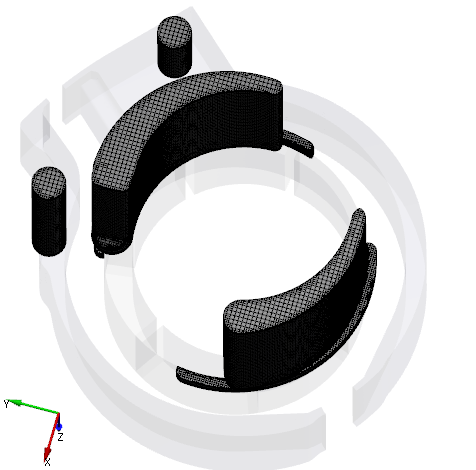
Figure 6.267 - Control, Groove, Port and Release mesh
|
|
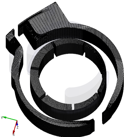
Figure 6.268 - Slider1, Slider2 and Rotor mesh
|
Create interfaces
In this section, the Mismatched Grid Interfaces (MGIs) are generated between boundaries.
The steps to create the MGIs are shown in below:
- Geometric Entities Panel > Volumes > Boundaries, select Boundaries as shown in Table 6.8.
- Click Connect Selected Boundaries via MGI
 icon to create the MGI entities refer, Figure 6.269.
A group display of entities can be viewed using the Group Entities by Volumes/Types  icon in Geometric Entities Panel toolbar.
| Control, groove,port,release, slider1 and slider2 |
control_mgi_slider, groove_axial_mgi, mgi_rotor_port_1, port_mgi_rotor_1, port_mgi_rotor_2, release_mgi_rotor, slider1_bot, slider2_bot |
MGI01 |
| Grooves and chamber wall |
chamber_wall , groove_mgi_chamber_wall
|
MGI02 |
Table 6.8 - Creating interfaces
The new entities are created under MGI in Volumes refer, Figure 6.270
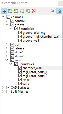
Figure 6.269 - Connecting grooves and chamber wall
|
|

Figure 6.270 - Created interfaces
|
| |
Note: If MGIs are created by connecting the wrong boundaries, delete the created MGIs by clicking on Delete Selected Geometric Entity icon and then recreate the MGIs. icon and then recreate the MGIs.
|