Defining Physics and Conditions
The physics and conditions are specified as follows.
Adding Modules
- Click Select Modules in the Model Panel. The Physical Model Selection dialog box opens.
- Vane is automatically added to the Model Panel by the Rotor Template Mesher.
- Select Circumferential Valve 1, click Delete.
- Select Cavitation under Available Modules list and click Add.
- Select Rotation (1 DOF) under Available Modules and click Add.
-
Click Close to close the Physical Model Selection dialog box.
|
|
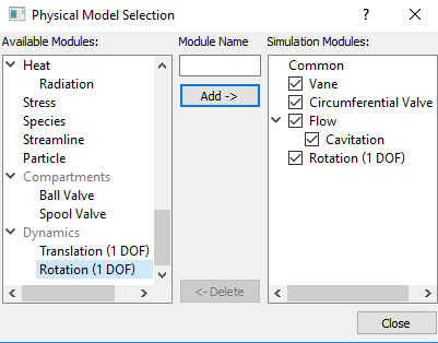
Figure 6.271 - Adding modules
|
| ´ |
Note: The Vane module and two Circumferential Valve modules were already added during the mesh creation and Flow will automatically be included. (The second Circumferential Valve module is not needed, since it has the same motion as the first. |
General Operating Parameters
- Select Vane in the Model Panel.
- Enter Number of Revolutions as 4 and Time Steps Per Vane Rotation as 40 for the Time Definition in the Model Tab of Properties Panel.
- Click Edit Expressions
 icon under Slider Rotation to open the Expression Editor dialog box. icon under Slider Rotation to open the Expression Editor dialog box.
- Enter the following for Global Expressions as follows (see, Figure 6.273).
pi = 3.1415927
angv = rotate_1d.angle*180/pi - 3.5
- Click OK and enter angv for the
Slider Rotation.
-
Enter the parameters for the Angular Velocity Definition as follows.
-
Rotational Direction: Clockwise
-
Rotational Speed: 3000 rpm
-
Rotational Axis Vector: 0, 0, 1
|
|
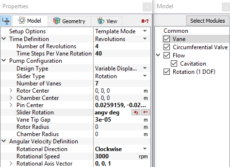
Figure 6.272 - Operating parameters
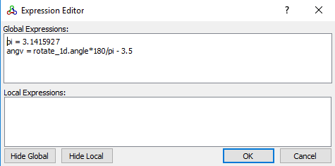
Figure 6.273 - angv expression
|
| |
Note:
-
The selection of a Time Steps Per Vane Rotation= 40 is critical for this problem because the dynamics module has an explicit component that is sensitive to the size of the time-step. Using the default value of 20 does not converge for this case.
- The value 3.5 in the expression is a pre-rotated angle included as adjustment to the original meshed position of the pumping chamber.
- The rotate_1d.angle is a variable generated by the Rotation (1 DOF) module that will link the position of the chamber wall with the dynamic motion of the outer Cam housing.
-
The Number of Vanes is used for calculating the time-step. (It does not change the geometry).
|
Circumferential Valve Operating Parameters
- Select Circumferential Valve in the Model Panel.
- Select Rotation (1 DOF) from Dynamics drop-down list in the Model Tab of Properties Panel. This links the motion of the Circumferential Valve to the value computed in the Rotation (1 DOF) module.
-
Enter the parameters for the Valve Configuration as follows.
|
|
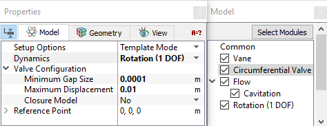
Figure 6.274 - Circumferential operating parameters
|
Rotation 1 (DOF) Operating Parameters
- Select Rotation (1 DOF) in the Model Panel.
- Select Force Balance in the Motion Type drop-down list.
-
Enter the parameters for Motion Type as follows.
| |
Note: Center of Rotation corresponds to Pin Center.
|
|
|
operatingparameters.png)
Figure 6.275 - Rotational 1 (DOF) operating parameters
|
Boundary Conditions
The boundary conditions are specified as follows.
Inlet and Control Inlet
- Select port_inlet from the port Boundaries list under Volumes in the Geometric Entities Panel.
- Select Inlet from Vane drop-down list in the Model Tab of Properties Panel.
-
Enter Inlet Pressure as 101325 Pa.
- Select control_inlet from the Boundaries list under Volumes in the Geometric Entities Panel.
- Select Inlet from the Vane drop-down list in the Model Tab of Properties Panel.
- Enter Inlet Pressure as 300000 Pa.
|
|
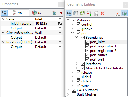
Figure 6.276 - Inlet conditions
|
Outlet and Release Outlet
-
Select port_outlet from the port Boundaries list under Volumes in the Geometric Entities Panel.
- Select Outlet from the Vane drop-down list in the Model Tab of Properties Panel.
- Enter Outlet Pressure as 1e+06 Pa.
- Select release_open from the Boundaries list under Volumes in the Geometric Entities Panel.
- Select Outlet from the Vane drop-down list in the Model Tab of Properties Panel.
- Enter Outlet Pressure as 101325 Pa.
|
|
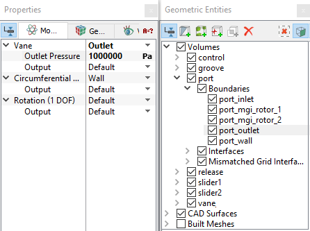
Figure 6.277 - Outlet conditions
|
Circumferential Valve Conditions Slider 1 and Slider 2
In this section, the boundary conditions for slider1 and slider2 are specified. The boundary conditions are preset by the Valve Template Mesher.
- Select Boundaries from the Geometric Entities Panel (see Table 6.9 ).
- In the Model Tab of Properties Panel, select boundary type in the Circumferential Valve drop-down list as listed in Table 6.9.
| slider1_bot, slider1_cyl_in, slider1_cyl_out, slider1_top
|
Cylinder
|
| slider1_ends
|
Valve End
|
| slider1_valve
|
Valve
|
| slider2_bot, slider2_cyl_in, slider2_cyl_out, slider2_top |
Cylinder
|
| slider2_ends
|
Valve End
|
| slider2_valve
|
Valve
|
Table 6.9 - Boundary type slider 1 and slider 2
Vane Pump Boundary Conditions
-
Select chamber_wall from the vane Boundaries list under Volumes in the Geometric Entities Panel.
- Select Chamber_wall from the Vane and Valve from the Circumferential Valve drop-down list in the Model Tab of Properties Panel.
- Select Dynamic BC from the Rotation (1 DOF) drop-down list.
- Select groove_wall from the groove Boundaries list in the Geometric Entities Panel.
- Select Groove or Side Gap from the Vane and Dynamic BC from the Rotation (1 DOF) drop-down list in the Model Tab of Properties Panel.
|
|
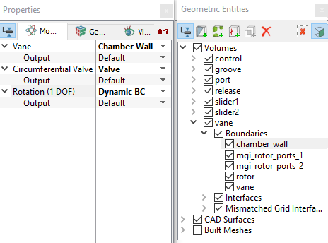
Figure 6.278 - Vane pump conditions
|
| |
Note: The Groove or Side Gap Boundary Conditions (BC) dictates that the associated groove volume will move with the same dynamics as Rotation (1 DOF).
|
Fluid Properties
- Select Volumes in the Geometric Entities Panel.
- In the Model Tab of Properties Panel
- Enter the parameters for Property list as follows.
- Material: Oil
- Dynamic Viscosity: 0.007 Pa-s
- Density: 800 kg/m3
- Liquid Bulk Modulus(B0): 1.5e+09 Pa
- Liquid Reference Pressure: 101325 Pa
- Saturation Pressure: 400 Pa
Enter the parameters for Operating Conditions as follows.
- Gas Mass Fraction: 9e-5 Pa-s
- Operating Temperature: 300 K
- Starting Pressure: 101325 Pa
|
|
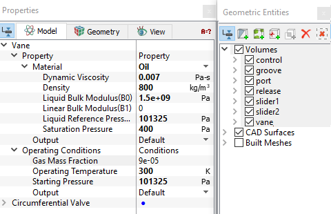
Figure 6.279 - Fluid properties
|