中文 English

Computational domain

This section explains the preparation of surfaces to create the domain. This is done with the operations splitting, combining and renaming of the surfaces.

Pump Surfaces
  1. Select CAD Surfaces pump in the Geometric Entities Panel.
  2. Select Split/Combine Geometry or Grid in the Mesh Panel.
  3. Select Split Disconnected from the Operation drop-down list in the Properties Panel, click Split Disconnected.
  4. Rename the six new CAD Surfaces pump_01, pump_02, pump_03, pump_04, pump_05 and pump_06 as inlet, chamber, outlet, groove1, groove2 and groove3 respectively in the Geometric Entities Panel.

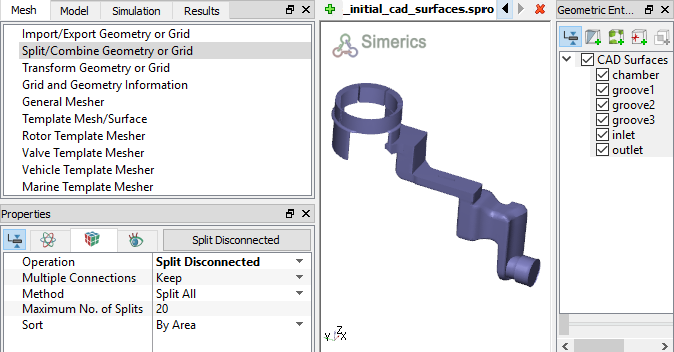
Figure 6.221 - Split of CAD surfaces


Inlet Surfaces
  1. Select CAD Surfaces inlet in the Geometric Entities Panel.
  2. Select Split by Angle from the Operation drop-down list in the Properties Panel.
  3. Enter 75 deg for Angle, click Split by Angle. Ten new CAD Surfaces are created.
  4. Rename the CAD Surfaces inlet_06 and inlet_08 as inlet_inlet and inlet_mgi respectively in the Geometric Entities Panel.
  5. Select the remaining inlet CAD Surfaces and select Combine from the Operation drop-down list in the Properties Panel.
  6. Click Combine and rename as inlet_walls.


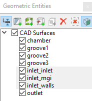
Figure 6.222 - Inlet surfaces

Rotor Surfaces
  1. Select CAD Surfaces chamber in the Geometric Entities Panel.
  2. Select Split by Angle from the Operation drop-down list in the Properties Panel.
  3. Enter 75 deg for Angle and 11 for Maximum No. of Splits, click Split by Angle. Twelve new CAD Surfaces are created in the Geometric Entities Panel.
  4. Select CAD Surfaces chamber and chamber_11, select Combine from the Operation drop-down list in the Properties Panel. Click Combine and rename as vanes.
  5. Select CAD Surfaces chamber_01 and rename as chamber_wall.
  6. Select CAD Surfaces chamber_02 and chamber_03, click Delete Selected Geometric Entity icon to delete the entities.
  7. Select CAD Surfaces chamber_04 to chamber_10, select Combine from the Operation drop-down list in the Properties Panel, click Combine and rename as rotor.


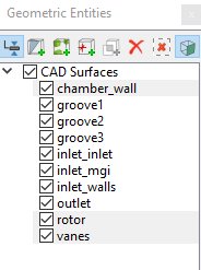
Figure 6.223 - Rotor surfaces

´ Note: The surfaces are deleted as they are not needed to create the chamber mesh.


Outlet Surfaces
  1. Select CAD Surfaces outlet in the Geometric Entities Panel.
  2. Select Split by Angle from the Operation drop-down list in the Properties Panel.
  3. Enter 75 deg for Angle, click Split by Angle. Three new CAD Surfaces are created in the Geometric Entities Panel.
  4. Rename the CAD Surfaces outlet_01, outlet_02 and outlet_03 as outlet_walls, outlet_mgi and outlet_outlet respectively.


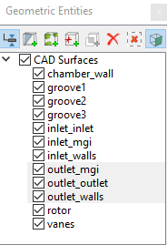
Figure 6.224 - Outlet surfaces

Groove surfaces
  1. Select CAD Surfaces groove1, groove2, and groove3 in the Geometric Entities Panel.
  2. Select Split by Angle from the Operation drop-down list in the Properties Panel.
  3. Enter 50 deg for Angle, click Split by Angle. Nine new CAD Surfaces are created in the Geometric Entities Panel.
  4. Select the CAD Surfaces groove1_01, groove2_01, and groove3_01, select Combine from the Operation drop-down list in the Properties Panel.
  5. Click Combine and rename groove1_01 as groove_walls. Similarly select the CAD Surfaces groove1_02, groove2_02 and groove3_02, click Combine and rename groove1_02 as groove_axial_mgi.
  6. Select the CAD Surfaces groove1_03, groove2_03 and groove3_03, click Combine and rename groove1_03 as groove_radial_mgi.


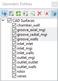
Figure 6.225 - Groove surfaces


Copyright © 2023 Simerics Inc.,