Building the Mesh
This section describes the step-by-step procedure for preparing the mesh for the vane pump. The Rotor Template Mesher is used for creating the chamber mesh and the General Mesher is used for the inlet, outlet and grooves.
Inlet and Outlet
- Select General Mesher in the Mesh Panel.
- Select CAD Surfaces inlet_inlet, inlet_mgi, inlet_walls, outlet_mgi, outlet_outlet and outlet_walls in the Geometric Entities Panel and click Add Surfaces
 icon for CAD Surfaces in the Properties Panel. icon for CAD Surfaces in the Properties Panel.
- Enter Maximum Cell Size as 0.01, Minimum Cell Size as 0.001 and Cell Size on Surfaces as 0.005.
- Click Create Mesh. A new mesh mesh is created under Built Meshes in the Geometric Entities Panel.
- To refine the interfaces, select mesh in Built Meshes and inlet_mgi, outlet_mgi from CAD Surfaces.
- Select User Input from Cell Size on Boundaries drop-down list and enter 0.0025 for Size in the Properties Panel. Click Create Mesh to update mesh under Built Meshes in the Geometric Entities Panel.
- The meshed volumes inlet and outlet are generated under Volumes.
|
|
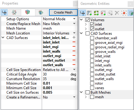
Figure 6.226 - Inlet and Outlet mesh settings
|
Rotor Chamber
- Select Rotor Template Mesher in the Mesh Panel.
- Select Advanced Mode from the Setup Options, Vane from the Rotor Type and Fixed Displacement from the Design Type drop-down list in the Properties Panel.
- Select CAD Surfaces rotor in the Geometric Entities Panel, click Add Surfaces icon for Rotor in the Properties Panel. Similarly select CAD Surfaces chamber_wall, click Add Surfaces for Chamber Wall.
-
Enter the parameters as follows.
- Click Build Vane Mesh. The new mesh vane is created under Built Meshes in the Geometric Entities Panel.
- The meshed volume vane is generated under Volumes.
|
|
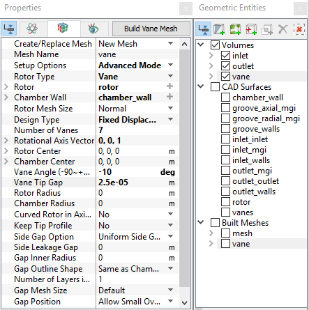
Figure 6.227 - Rotor mesh settings
|
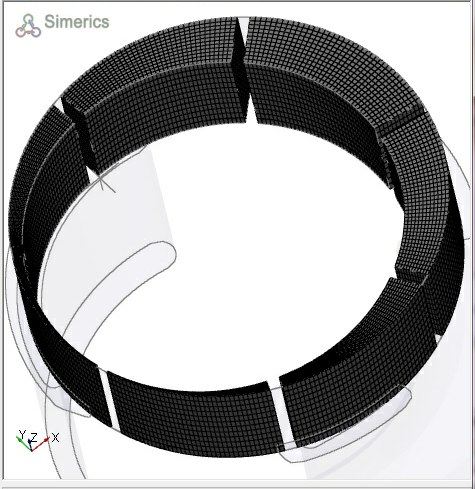
Figure 6.228 - Rotor chamber
|
|
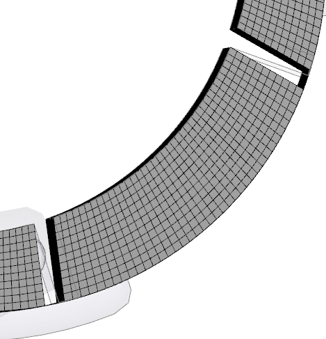
Figure 6.229 - Rotor tip gap
|
| ´ |
Note:
- Figure 6.229 shows that the blades are slanted, and there is a mesh in the tip gap
- Once created, the tip gap can be changed during the simulation under the Model Panel. The number of cells in the tip gap can be modified by using User Input for theRotor Mesh Size during the meshing operation.
- The slant of the blades (positive vs. negative) is based on the right-hand rule, relative to the Rotational Axis Vector.
|
Groove Mesh
- Select General Mesher in the Mesh Panel.
- Select grooves CAD Surfaces in the Geometric Entities Panel and Enter Maximum Cell Size as 0.01, Minimum Cell Size as 0.001 and Cell Size on Surfaces as 0.0025 in the Properties Panel.
- Click Create Mesh. A new mesh groove is created under Built Meshes and groove, groove_1 and groove_2 are generated under Volumes in the Geometric Entities Panel.
-
To refine the interfaces, select groove in Built Meshes and groove_axial_mgi, groove_radial_mgi under CAD Surfaces. Select User Input from Cell Size on Boundaries drop-down list and enter 0.00125 for Size in the Properties Panel. Click Create Mesh to update groove under Built Meshes in the Geometric Entities Panel.
- Select Split/Combine Geometry or Grid in the Mesh Panel.
- Select groove, groove_1 and groove_2 sequentially under Volumes in the Geometric Entities Panel. Select Combine from the Operation drop-down list in the Properties Panel, click Combine.
- Select groove_axial_mgi, groove_axial_mgi_1, groove_axial_mgi_2 sequentially under Boundaries and click Combine.
- Select groove_radial_mgi, groove_radial_mgi_1, groove_radial_mgi_2 sequentially under Boundaries, click Combine. Similarly select groove_walls, groove_walls_1 and groove_walls_2 sequentially under Boundaries, click Combine.
- The meshed volume groove is generated under Volumes.
|
|
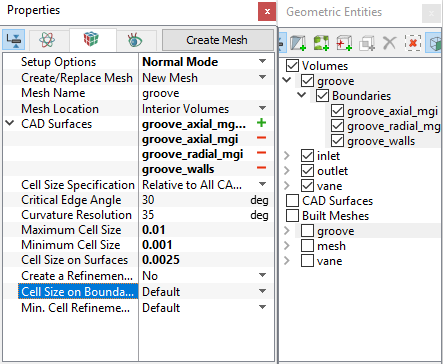
Figure 6.230 - Groove mesh settings
|
The mesh created for the fluid domain is shown below.
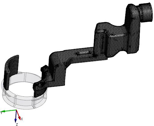
Figure 6.231 - Inlet and Outlet mesh
|
|
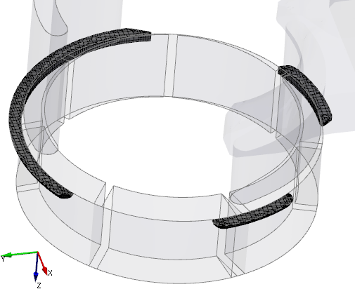
Figure 6.232 - Groove mesh
|
Create interfaces
In this section, the Mismatched Grid Interfaces (MGIs) are generated between boundaries.
The steps to create the MGIs are shown below:
- Geometric Entities Panel > Volumes > Boundaries, select Boundaries as shown in Table 6.4.
- Click Connect Selected Boundaries via MGI
 icon to create the MGI entities refer, Figure 6.233.
A group display of entities can be viewed using the Group Entities by Volumes/Types  icon at Geometric Entities Panel toolbar.
| Inlet, outlet, rotor chamber and grooves |
groove_axial_mgi, inlet_mgi, mgi_rotor_ports_1, and outlet_mgi |
MGI01 |
| Rotor chamber and grooves |
chamber_wall and groove_radial_mgi |
MGI02 |
Table 6.4 - Creating interfaces
The new entities are created under MGI in Volumes refer, Figure 6.234.
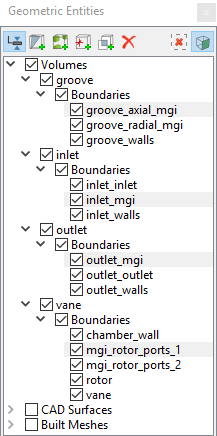
Figure 6.233 - Connecting interfaces
|
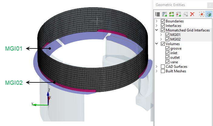
Figure 6.234 - Created interfaces
|
| |
Note: If MGIs are created by connecting the wrong boundaries, delete the created MGIs by clicking on Delete Selected Geometric Entity  icon and then recreate the MGIs. icon and then recreate the MGIs.
|