|
You are here: Additional Templates and Tutorials > GT-SUITE Coupling Module and Tutorial > GT Coupling Tutorials > Specifying Interface conditions
|
Specifying Interface conditions
In this step, the interfaces in the GT-SUITE corresponding to the Inlet and Outlet in the fluid CFD model are linked to create appropriate boundary conditions for the CFD simulation.
Inlet Interface
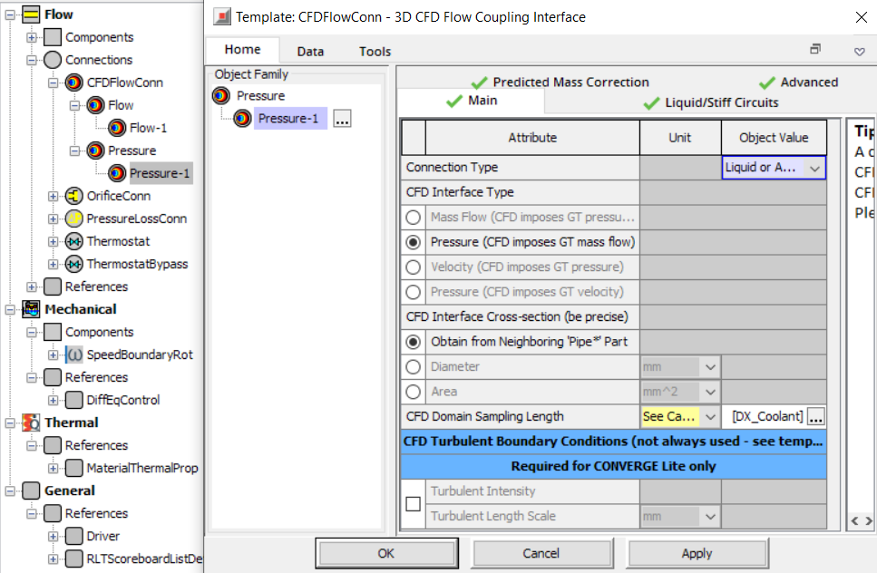
To create an inlet interface in GT-SUITE, the CFDFlowConn object Pressure-1 is created and specified with the following connection related parameters as shown in Figure 10.116 and Figure 10.117.
- Select Pressure – 1 under Connections – CFDFlowConn – Pressure.
- Select the Main tab in the 3D CFD Flow Coupling Interface dialog box.
- Select Liquid or Advanced for Connection Type.
- Select Pressure (CFD imposes GT mass flow) under CFD Interface Type.
- Select DX_Coolant under CFD Domain Sampling Length.
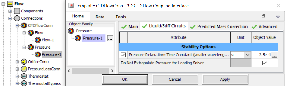
- Select the Liquid/Stiff Circuits tab in the 3D CFD Flow Coupling Interface dialog box.
- Set the Object Value as 2.5e-04 for Pressure Relaxation Time Constant (smaller wavelengths damped).
|
Note: The Pressure Relaxation Time Constant is used as a high frequency filter to filter out spurious oscillations in the 1D simulation compared to the 3D simulation. The relaxation time should not exceed 1/6 of the cycle time as a best practice. |
The Pressure Relaxation Time Constant option is enabled only when the Liquid or Advanced option is selected for Connection Type.
Outlet Interface
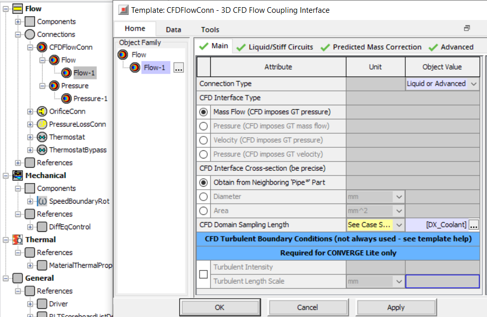
To create an outlet interface in GT-SUITE, the CFDFlowConn object Flow-1 is created and specified with the following connection related parameters as shown in Figure 10.118 and Figure 10.119.
- Select Flow – 1 under Connections – CFDFlowConn – Flow.
- Select the Main tab in the 3D CFD Flow Coupling Interface dialog box.
- Select Liquid or Advanced for Connection Type.
- Select Mass Flow (CFD imposes GT pressure) under CFD Interface Type.
- Select DX_Coolant under CFD Domain Sampling Length.
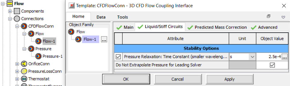
- Select the Liquid/Stiff Circuits tab in the 3D CFD Flow Coupling Interface dialog box.
- Set the Object Value as 2.5e-04s for Pressure Relaxation Time Constant (smaller wavelengths damped).
|
Note: The Pressure Relaxation Time Constant is used as a high frequency filter to filter out spurious oscillations in the 1D simulation compared to the 3D simulation. The relaxation time should not exceed 1/6 of the cycle time as a best practice. |
The Pressure Relaxation Time Constant option is enabled only when the Liquid or Advanced option is selected for Connection Type.