Contours
The most common contours for the cabin radiation simulation are the temperature and the velocity contours across the domain. The steps to create contours are:
- Click Load Results in the Simulation Panel.
- Select the required result file in the ensuing Load Results dialog box, click Open.
Create a section
A section is created with the following steps:
- Click Create a Cross-Section
 icon twice in the Geometric Entities Panel. New sections Section 01 and Section 02 are created under Derived Surfaces.
 - Select Section 01, the Type and Position are specified as Plane X and 0 mrespectively in the Geometry Tab of Properties Panel.
- Select Section 02, the Type and Position are specified as Plane Y and 0 m respectively.
Velocity magnitude Contours
- Select Section 01 and Section 02 under Derived Surfaces in the Geometric Entities Panel.
- Under Volumes > cabin > Boundaries, select cabin_chair and cabin_table along with other sections.
- Select Velocity Magnitude under Derived Variables list for the Variable drop-down list in the Results Panel. For variables and legends, refer Post-Processing.
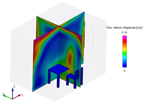
Figure 11.144 - Velocity magnitude
Density Contours
- Select Section 02 under Derived Surfaces in the Geometric Entities Panel.
- Select Density under Properties list for the Variable drop-down list in the Results Panel.
- Under Volumes > cabin > Boundaries, select cabin_table along with section in the Geometric Entities Panel.
-
Select Velocity under Variables list for the Vector drop-down list of the View Tab of Properties Panel.
-
Set the following parameters for the vectors:
- Size - 3
- Head Size - 0.15
- Projection - Yes
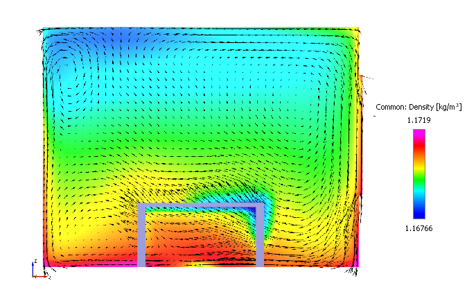
Figure 11.145 - Density contour
Temperature Contours
- Select cabin under Volumes in the Geometric Entities Panel.
- Select Temperature under Variables list for the Variable drop-down list in the Results Panel. For variables and legends, refer Post-Processing.
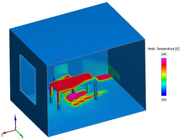
Figure 11.146 - Temperature contour