Defining Physics and Conditions
The physics and conditions are specified as follows.
Add Modules
- Click Select Modules in the Model Panel. The Physical Model Selection dialog box opens.
- Select Turbulence in the Available Modules list and click Add.
- Select Radiation in the Available Modules list and click Add.
- Select Streamline in the Available Modules list and click Add.
-
Click Close, to close the Physical Model Selection dialog box.
|
|
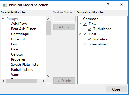
Figure 11.132 - Adding modules
|
Operating Parameters
Flow
- Select Flow in the Model Panel as shown in Figure 11.133.
- Set the value of Convergence Criterion to 1e-06.
- Select Yes for Gravity Force drop-down list.
- Enter 0, 0, -9.8 m/s2 for
 in the Gravity Force list. in the Gravity Force list.
|
|
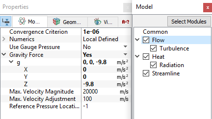
Figure 11.133 - Flow operating parameters
|
Radiation
- Select Radiation in the Model Panel as shown in Figure 11.134.
-
Select Parallel Source for the Source list.
- Enter -1, -0.3, -0.5 for the Direction under Source list.
- Enter 500 for Power Density in W/m2.
|
|
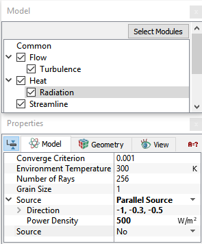
Figure 11.134 - Radiation operating parameters
|
Boundary Conditions
The boundary conditions are specified as follows.
Inner Walls
- Select cabin_front_wall and cabin_inner_wall from the Boundaries list in the Geometric Entities Panel.
- Select Convection/Radiation for Heat drop-down list in the Model Tab of Properties Panel.
- Select Convection/Radiation for Options drop-down list.
- Enter 50 for Exchange Coefficient under the Options drop-down list.
- Enter 1 for Emissivity under the Options drop-down list.
- Select User Select for Output drop-down list.
- Select Yes for Total Flux in Output drop-down list.
|
|
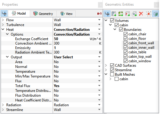
Figure 11.135 - Inner wall conditions
|
Top Walls
- Select cabin_top_wall from the Boundaries list in the Geometric Entities Panel.
- Select Convection/Radiation for Heat drop-down list in the Model Tab of Properties Panel.
-
Select Convection/Radiation for Options drop-down list.
- Enter 100 for Exchange Coefficient under the Options drop-down list.
- Enter 1 for Emissivity under the Options drop-down list.
- Select User Select for Output drop-down list.
- Select Yes for Total Flux in Output drop-down list.
|
|
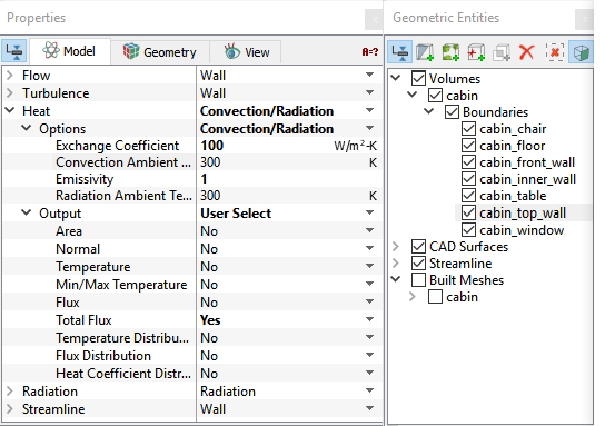
Figure 11.136 - Top wall conditions
|
Window
- Select cabin_window from the Boundaries list in the Geometric Entities Panel.
- Select Convection/Radiation for Heat drop-down list in the Model Tab of Properties Panel.
-
Select Convection for Heat drop-down list.
- Enter 200 for Exchange Coefficient under the Options drop-down list.
- Select User Select for Output drop-down list.
- Select Yes for Total Flux in Output drop-down list.
- Select Transparent for Radiation drop-down list
|
|
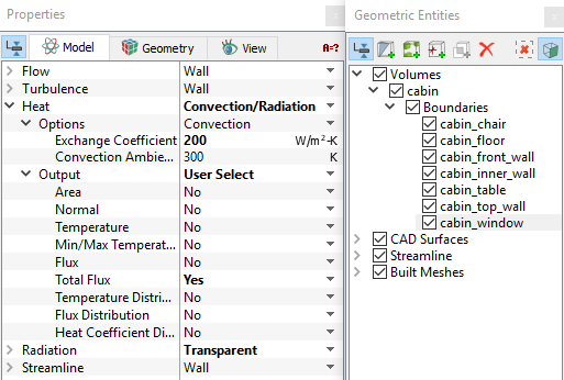
Figure 11.137 - Window conditions
|
Table
- Select cabin_table from the Boundaries list in the Geometric Entities Panel.
- Select Yes for Release Particle drop-down list under Streamline in the Model Tab of Properties Panel.
- Select Both for Direction drop-down list
- Enter 1 for Number of Particles.
- Select Cell Center for Release Position drop-down list.
|
|
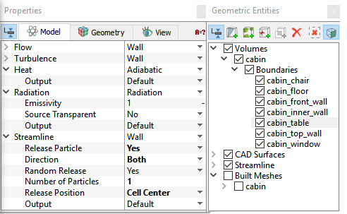
Figure 11.138 - Table conditions
|
Fluid Properties
- Select Volumes in the Geometric Entities Panel.
- Select Ideal Gas Law under Density drop-down list in the Common list.
|
|
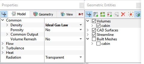
Figure 11.139 - Fluid properties
|