Contours
The pressure and the temperature contours are created across the domain as follows:
- Click Load Results in the Simulation Panel.
- Select the required result file in the ensuing Load Results dialog box, click Open.
Pressure Contours
- Select all Boundaries of fluid_domain under Volumes in the Geometric Entities Panel.
- Select fluid_domain_Chip_thermal, fluid_domain_Heat_sink1, fluid_domain_Heat_sink2, fluid_domain_Heat_sink3, fluid_domain_PCB, fluid_domain_Transformer, fluid_domain_Transistor1, fluid_domain_Transistor2, fluid_domain_Transistor3 and fluid_domain_Transistor4 under Interfaces of fluid_domain under Volumes.
- Select Surface as Yes under View Tab of Properties Panel.
- Select Pressure [Flow] from Display Variable drop-down list in the View Tab of Properties Panel.
|
Note: The legend for the plot can be adjusted using the Min and Max in the Properties Panel. |
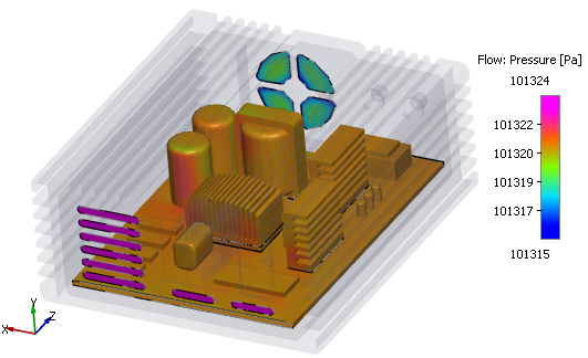
Figure 11.45 - Pressure contours
Temperature Contours
- Select all Boundaries of fluid_domain under Volumes in the Geometric Entities Panel.
- Select fluid_domain_Chip_thermal, fluid_domain_Heat_sink1, fluid_domain_Heat_sink2, fluid_domain_Heat_sink3, fluid_domain_PCB, fluid_domain_Transformer, fluid_domain_Transistor1, fluid_domain_Transistor2, fluid_domain_Transistor3 and fluid_domain_Transistor4 under Interfaces of fluid_domain under Volumes.
-
Select Surface as Yes under View Tab of Properties Panel.
- Select Temperature [Heat] from Display Variable drop-down list in the View Tab of Properties Panel.
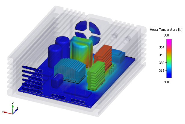
Figure 11.46 - Temperature contours