Building the Mesh
This section describes the step-by-step procedure to prepare the mesh and interfaces for conjugate heat transfer in a power inverter. The creation of multiple interfaces is time consuming if it is created manually between each fluid and solid volumes. In Simerics-MP, CAD surfaces are imported, and mesh is generated for all the fluid and solid volumes along with their interfaces automatically.
Create Mesh
|
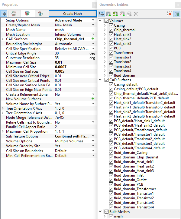
Figure 11.28 - Create mesh
|
| Volume | Rename as |
|---|---|
| volume | Casing |
| volume_01 | PCB |
| volume_02 | Transformer |
| volume_03 | Heat_sink2 |
| volume_04 | Heat_sink3 |
| volume_05 | Heat_sink1 |
| volume_06 | Chip_thermal |
| volume_07 | Transistor2 |
| volume_08 | Transistor4 |
| volume_09 | Transistor1 |
| volume_10 | Transistor4 |
Table 11.1 - Rename mesh volume
The created mesh is shown below.
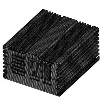
Figure 11.29 - Casing (solid) |
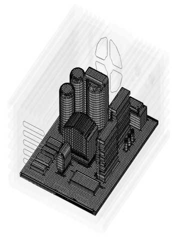
Figure 11.30 - Components (solid) |
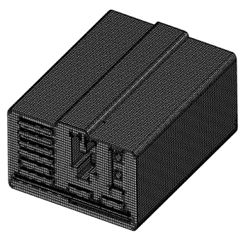
Figure 11.31 - Fluid volume |