Defining Physics and Conditions
The physics and conditions are specified as follows.
Add Modules
|
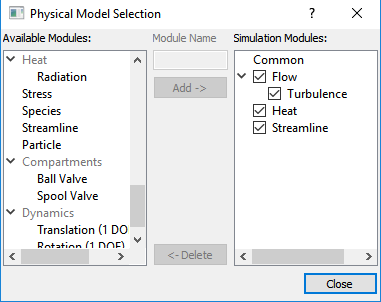
Figure 11.32 - Adding modules |
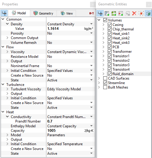
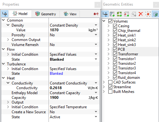
Chip, Casing and Heat sinks
|
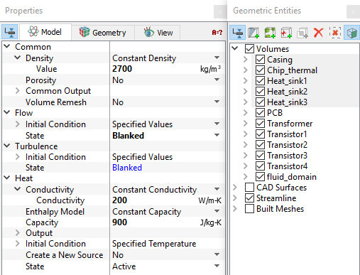
PCB and Transformer
|
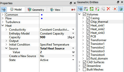
Transistors
|
Figure 11.38 - Transistors properties
|
Boundary conditions
The boundary conditions are specified as follows:
Inlet
|
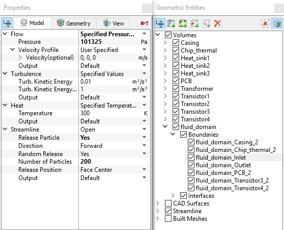
Figure 11.39 - Inlet conditions |
Outlet
|
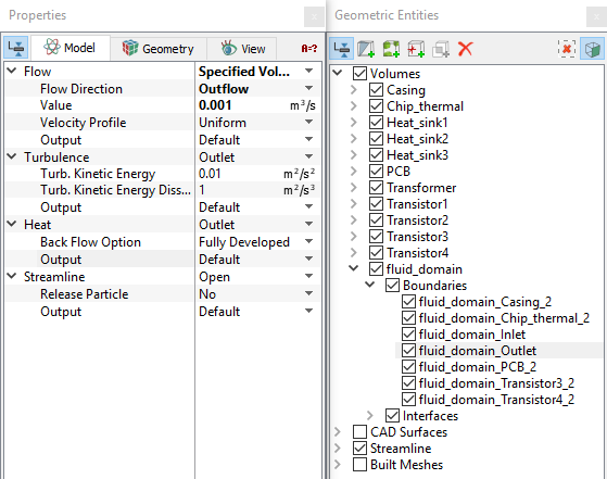
Figure 11.40 - Outlet conditions |