Building the Mesh
This section describes the step-by-step procedure to prepare the mesh and interfaces for conjugate heat transfer in a EGR cooler. The creation of multiple interfaces is time consuming if it is created manually between each fluid and solid volumes. In Simerics-MP, CAD surfaces are imported, and mesh is generated for all the fluid and solid volumes along with their interfaces automatically. If the openings of the imported domain are not closed, then they can be closed in Simerics-MP using bounding box. The bounding box is created during meshing.
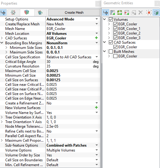
| Note: The volume created by bounding box margins should be deleted. Since it is used to close the opening of the domain and not used in simulation. |
The created mesh is shown below.
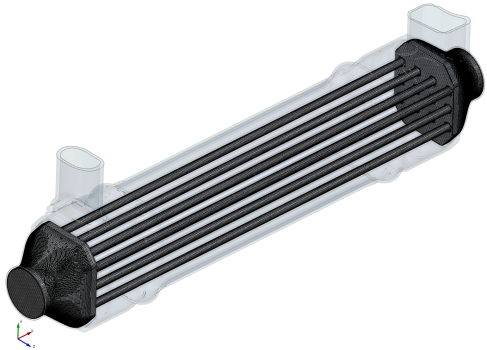
Figure 11.53 - Air volume mesh |
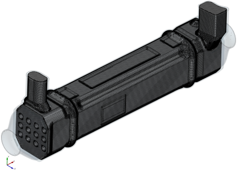
Figure 11.54 - Coolant volume mesh |
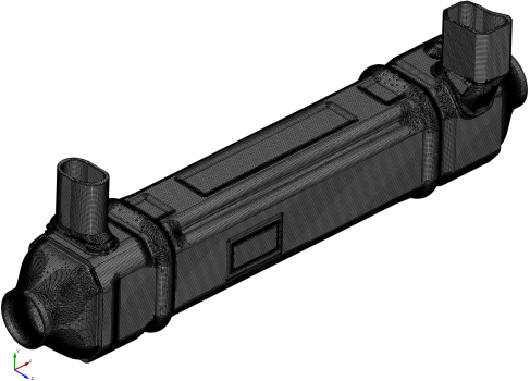
Figure 11.55 - Metal mesh |
Rename Boundaries
- Under Volumes > Air > Boundaries, select outside_dir1_max_1, outside_dir1_min_1 and rename as Air_outlet, Air_inlet respectively.
- Under Volumes > Coolant > Boundaries, select outside_dir2_max_1.
-
Select Split Disconnected from the Operation drop-down list in the Properties Panel, click Split Disconnected.
-
Rename the two new Boundaries outside_dir2_max_1_01 and outside_dir2_max_1_02 as Coolant_outlet and Coolant_inlet respectively in the Geometric Entities Panel.