Defining Physics and Conditions
The physics and conditions are specified as follows.
Add Modules
- Click Select Modules in the Model Panel. The Physical Model Selection dialog box opens.
- Select Turbulence under Available Modules list and click Add.
- Select Heat under Available Modules list and click Add.
- Select Streamline under Available Modules list and click Add.
- Select Streamline under Available Modules list, enter Module Name as 2 and click Add.
-
Click Close to close the Physical Model Selection dialog box.
|
|
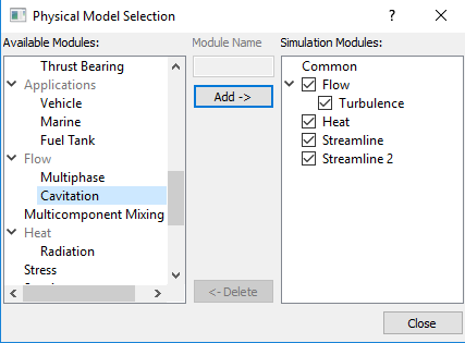
Figure 11.56 - Adding modules
|
| |
Note: If the same physical module is being added multiple times into the Simulation Panel, it is mandatory to enter the name of the additional module. After giving the additional module name under Module Name, it will add as a suffix to the default name of the module . |
Properties
Air
- Select Air under Volumes in the Geometric Entities Panel.
-
Enter 1.1766 kg/m3 for Value under the Density drop-down list in the Model Tab of Properties Panel.
- Enter 1.853e-5 Pa-s for Value under the Flow > Viscosity drop-down list.
- Enter 0.7 for Prandtl Number under the Heat > Conductivity list.
-
Enter 1005 J/kg-K for Capacity under Heat.
|
|
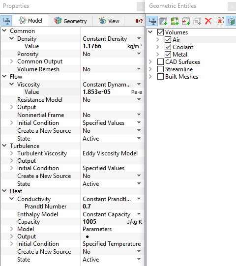
Figure 11.57 - Properties for air
|
Coolant
- Select Coolant under Volumes in the Geometric Entities Panel.
-
Enter 1000 kg/m3 for Value under Density drop-down list in the Model Tab of Properties Panel.
- Enter 0.001 Pa-s for Value under the Flow > Viscosity drop-down list.
- Select Constant Conductivity from the Conductivity drop-down list and enter 0.4W/m-K for Conductivity under the Heat list.
-
Enter 3739 J/kg-K for Capacity under Heat list.
|
|
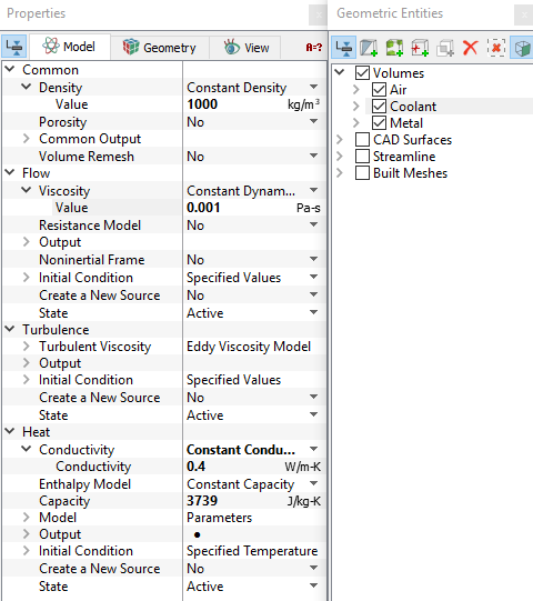
Figure 11.58 - Properties for coolant
|
Metal
- Select Metal under Volumes in the Geometric Entities Panel.
-
Enter 8030 kg/m3 for Value under Density drop-down list in the Model Tab of Properties Panel.
-
Select Blanked for State drop-down list under Flow .
-
Enter 16.2W/m-K for Conductivity under the Heat > Conductivity list.
-
Enter 500 J/kg-K for Capacity under Heat.
|
|
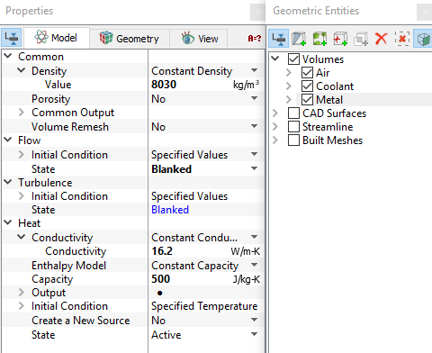
Figure 11.59 - Properties for metal
|
| |
Note: Setting the Flow > State to Blanked turns off the solution of the flow in that volume.
|
Boundary conditions
The boundary conditions for Air under Volumes are specified as follows:
Inlet
- Select Air_inlet from the Boundaries list in the Geometric Entities Panel.
- Select Specified Volumeric Flux from the Flow drop-down list in the Model Tab of Properties Panel.
- Select Inflow from the Flow Direction drop-down list.
-
Enter 0.1m3/s for Value under Flow.
-
Select User Select for Output under Flow list.
- Select Yes for Average Static Pressure drop-down list under Flow > Output list.
- Enter 500K for Temperature under Heat list.
- Select User Select for Output under Heat list.
- Select Yes for Temperature, Min/Max Temperature and Total Flux drop-down list under Heat > Output list.
-
Select Yes for Release Particle under Streamline list.
-
Enter 150 as Number of Particles under Streamline list.
|
|
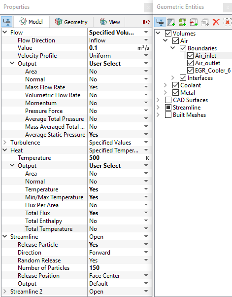
Figure 11.60 - Inlet conditions
|
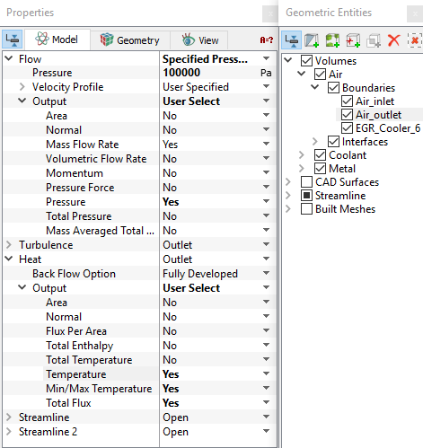
Outlet
- Select Air_outlet from the Boundaries list in the Geometric Entities Panel.
- Select Specified Pressure Outlet from the Flow drop-down list in the Model Tab of Properties Panel.
- Enter 100000 Pa for Pressure under Flow list.
- Select User Select for Output under Flow list.
- Select Yes for Pressure drop-down list under Flow > Output list.
- Select User Select for Output under Heat list.
-
Select Yes for Temperature, Min/Max Temperature and Total Flux drop-down list under Heat > Output list.
|
|
Figure 11.61 - Outlet conditions
|
The boundary conditions for Coolant under Volumes are specified as follows:
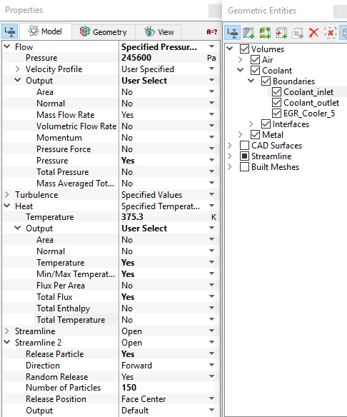
Inlet
-
Select Coolant_inlet from the Boundaries list in the Geometric Entities Panel.
-
Select Specified Pressure Inlet from the Flow drop-down list in the Model Tab of Properties Panel.
-
Enter 2.456e5 Pa for Pressure under Flow list.
-
Select User Select for Output under Flow list.
- Select Yes for Pressure drop-down list under Flow > Output list.
- Select Specified Temperature from Heat drop-down list.
-
Enter 375.3 K for Temperature under Heat list.
- Select User Select for Output under Heat list.
-
Select Yes for Temperature, Min/Max Temperature and Total Flux drop-down list under Heat > Output list.
- Select Yes for Release Particle under Streamline 2 list.
- Enter 150 as Number of Particles under Streamline 2 list.
|
|
Figure 11.62 - Inlet conditions
|
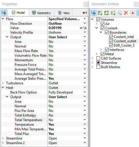
Outlet
- Select Coolant_outlet from the Boundaries list in the Geometric Entities Panel.
- Select Specified Volumeric Flux from the Flow drop-down list in the Model Tab of Properties Panel.
- Select Outflow from the Flow Direction drop-down list.
-
Enter 0.00199 m3/s for Value under Flow.
-
Select User Select for Output under Flow list.
- Select Yes for Average Static Pressure drop-down list under Flow > Output list.
- Select User Select for Output under Heat.
-
Select Yes for Temperature, Min/Max Temperature and Total Flux drop-down list under Heat > Output list.
|
|
Figure 11.63 - Outlet conditions
|