Contours
The steps to create contours are:
- Click Load Results in the Simulation Panel.
- Select the required result file in the ensuing Load Results dialog box, click Open.
Isosurface contours
The Iso-surface shows the region of a specified range of Velocity X. These regions are colored with pressure.
- Click Create an Isosurface
 icon in the Geometric Entities Panel. An Isosurface 01 is created under Derived Surfaces.
 - Select Isosurface 01 under Derived Surfaces.
- Select Velocity X [m/s] Flow from the Variables list in the Isosurface Variable drop-down list in the Geometry Tab of Properties Panel.
- Select Below Value from the Option drop-down list.
- Ensure that the Value is set to 0 m/s.
- Switch to View Tab of Properties Panel and specify the values as follows:
- Select Pressure [Pa] Flow for Display Variable drop-down list.
- Enter -75 for Minimum.
- Enter 0 for Maximum.
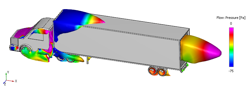
Figure 11.193 - Isosurface of Velocity overlay by Pressure