- Select General Mesher in the Mesh Panel.
- Select all CAD Surfaces in the Geometric Entities Panel and click Add Surfaces
 icon for CAD Surfaces in the Properties Panel. icon for CAD Surfaces in the Properties Panel.
- Select Exterior Volumes from the Mesh Location drop-down list.
- Select Nonuniform from Bounding Box Margins drop-down list and enter the values as follows:
- Minimum Side Sizes: 0.3, 0, 1.5
- Maximum Side Sizes: 2.0, 1.2, 1.5
- Enter 0.0005 for Minimum Cell Size.
- Select Box Zone Refinement from Create a Refinement Zone drop-down list and specify the following parameters under Refine Zone Options extended list:
- Enter 0.005 for Cell Size
- Enter -9.0, -1.0, -1.5 for First Corner
- Enter 11.0, 4.0, 1.5 for Diagonal Corner
- Select CAB under CAD Surfaces in the Geometric Entities Panel.
- Select User Input from Cell Size on Boundaries drop-down list in the Properties Panel.
- Enter 0.00125 for Size under Cell Size on Boundaries.
- Select Advanced Mode for Setup Options and then, select Combined with Patches for Sub-feature Options.
- Click Create Mesh. A new mesh mesh is created under Built Meshes in the Geometric Entities Panel.
- The meshed Volume volume is generated under Volumes.
|
|
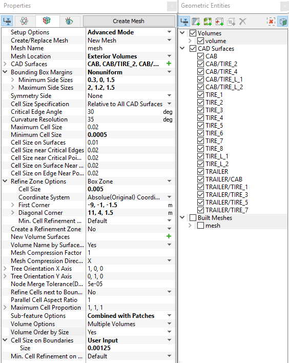
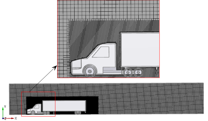
Figure 11.182 - Mesh settings
|