中文 English
You are here: Tutorials > External Aerodynamics > Setting up the model > Defining Physics and Conditions

Defining Physics and Conditions

The physics and conditions are specified as follows:
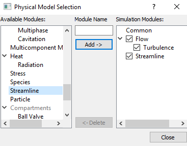
Add Modules
  1. Click Select Modules in the Model Panel. The Physical Model Selection dialog box opens.
  2. Select Turbulence under Available Modules list and click Add.
  3. Select Streamline under Available Modules list and click Add.
  4. Click Close to close the Physical Model Selection dialog box.
 

Figure 11.184 - Adding modules

Boundary conditions

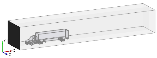
The boundary conditions are specified to the surfaces of the bounding box.

Inlet

The inlet boundary conditions are specified as follows:

  1. Select outside_dir1_min from the Boundaries list under Volumes in the Geometric Entities Panel.
  2. Select Specified Velocity from the Flow drop-down list in the Model Tab of Properties Panel.
  3. Enter 20,0,0 m/s for Velocity under Method.

Figure 11.185 - Inlet boundary


Figure 11.186 - Inlet boundary conditions


Outlet

The outlet boundary conditions are specified as follows:

  1. Select outside_dir1_max from the Boundaries list under Volumes in the Geometric Entities Panel.
  2. Select Specified Pressure Outlet from the Flow drop-down list in the Model Tab of Properties Panel.
  3. Ensure Pressure is set to 0 Pa.

Figure 11.187 - Outlet boundary


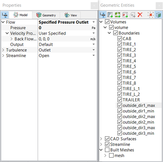
Figure 11.188 - Outlet boundary conditions
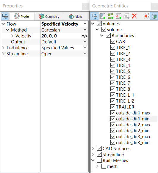
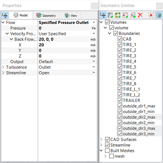
 

Other boundaries

The conditions to the other boundaries are specified as follows:

  1. Select outside_dir2_max, outside_dir3_max and outside_dir3_min from the Boundaries list under Volumes in the Geometric Entities Panel.
  2. Select Specified Pressure Outlet from the Flow drop-down list in the Model Tab of Properties Panel.
  3. Enter 20,0,0 m/s for Back Flow Velocity(optional) under Velocity Profile in the Model Tab of Properties Panel.

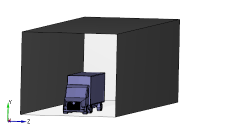
Figure 11.189 - Other boundaries


Figure 11.190 - Other boundary conditions


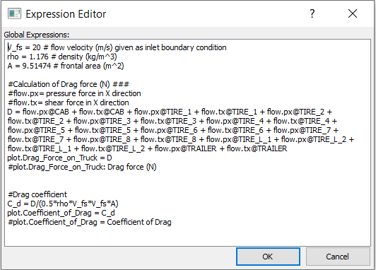
Expressions for calculation of drag coefficient

To calculate the drag forces and drag coefficient on the truck using expressions, do the steps as follows:

  1. Select all Volumes in the Geometric Entities Panel.
  2. Click Edit expressions icon in the Toolbar. A Expression Editor dialog box appears on the graphics area.
  3. Enter or copy and paste the expressions written under Description drop-down list for Global Expressions, as shown in Figure 11.191.
  4. Click OK to close Expression Editor box.
 

Note: The value of V_fs needs to be changed in the Expression Editor depending on the value assigned under Specified Velocity as the inlet boundary condition.


Figure 11.191 - Expression for drag calculation


Copyright © 2023 Simerics Inc.,