Contours
The most common contours for the heated disk simulation are the pressure and the velocity contours across the domain. The steps to create contours are:
- Click Load Results in the Simulation Panel.
- Select the required result file in the ensuing Load Results dialog box, click Open.
Create a section
A section is created with the following steps.
- Click Create a Cross-Section
 icon in the Geometric Entities Panel. A new section Section 01 is created under Derived Surfaces.
 - Select Section 01, the Type and Position are specified as Plane Y and -0.002 m in the Geometry Tab of Properties Panel.
Create an Isosurface
An isosurface is created with the following steps.
- Click Create an Isosurface
 icon in the Geometric Entities Panel. An Isosurface 01 is created under Derived Surfaces.
 - Select Temperature [Heat] under Variables for the Isosurface Variable drop-down list in the Geometry Tab of Properties Panel.
- Select Below Value from the Option drop-down list.
- Enter 302 K for Value.
Temperature Contours
- Select Section 01 under Derived Variables in the Geometric Entities Panel.
- Select Temperature under Variables list for the Variable drop-down list in the Results Panel.
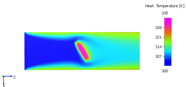
Figure 11.91 - Temperature contours
Velocity Streamline
- Click Select Modules in the Model Panel, to open Physical Model Selection dialog box.
- Select Streamline in the Available Modules list and click Add.
-
Click Close to close the Physical Model Selection dialog box. Streamline is added in the Geometric Entities Panel.
- Select the Boundaries inlet under pipe Volumes.
- Select Yes from the Streamline drop-down list and enter 50 for the Release Particle and Number of Particles in the Model Tab of Properties Panel.
- Select Streamline in the Geometric Entities Panel.
- Enter 0.001 for Line Thickness and 10 for Animation Time Size .
- Select disk under Volumes and Streamline in the Geometric Entities Panel.
- Select Velocity Magnitude from the Derived Variables list in the Variable drop-down list of Results Panel.
Figure 11.92 - Velocity streamline contour
Velocity on Isosurface Contours
- Select Isosurface 01 under Derived Surfaces.
- Select Velocity Magnitude from the Derived Variables list in the Variable drop-down list of Results Panel.
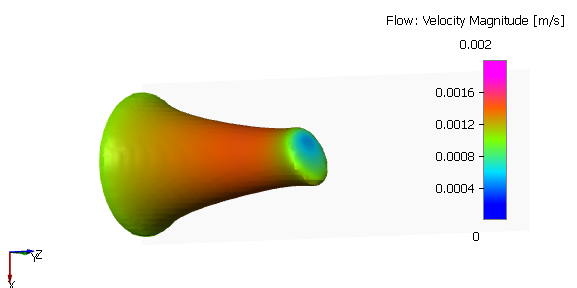
Figure 11.93 - Velocity on isosurface contours
Temperature and Velocity vectors
- Click Create a Cross-Section icon in the Geometric Entities Panel. A new section Section 02 is created under Derived Surfaces.
- Select Section 02, the Type is specified as Plane X and 0 m in the Geometry Tab of Properties Panel.
- Select Keep Negative Side from the Section Option drop-down list in the View Tab of Properties Panel.
- Select outlet under Boundaries in the Geometric Entities Panel.
- Select Temperature under Variables list from the Vector drop-down list in the View Tab of Properties Panel.
- Enable Vectors and enter 340 for Max in the Results Panel.
-
Enter parameters for the Vector drop-down list in the View Tab of Properties Panel as follows.
- Color: Black
- Size: 3
- Head Size: 0.5
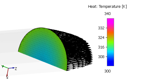
Figure 11.94 - Temperature and Velocity vectors