中文 English
You are here: Tutorials > Multicomponent Mixing > Setting up the model > Computational domain

Computational domain

This section explains the preparation of surfaces to create the domain. This is done with the operations splitting, combining and renaming of the surfaces.

Fuel Pipe Surfaces
  1. Select CAD Surfaces fuelpipe in the Geometric Entities Panel.
  2. Select Split by Angle from the Operation drop-down list in the Properties Panel.
  3. Enter 75 deg for Angle and click Split by Angle. Three new CAD Surfaces are created in the Geometric Entities Panel.
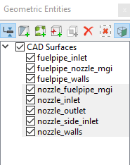
  4. Select CAD Surfaces fuelpipe_01, fuelpipe_02 and fuelpipe_03, rename them as fuelpipe_walls, fuelpipe_inlet and fuelpipe_nozzle_mgi respectively.

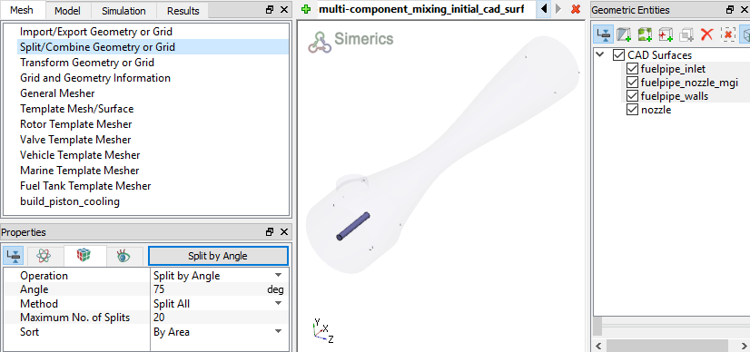
Figure 11.151 - Fuel pipe surfaces


Nozzle Surfaces
  1. Select CAD Surfaces nozzle in the Geometric Entities Panel.
  2. Select Split by Angle from the Operation drop-down list in the Properties Panel.
  3. Enter 75 deg for Angle, click Split by Angle. Six new CAD Surfaces are created in the Geometric Entities Panel.
  4. Select CAD Surfaces nozzle_02nozzle_03, nozzle_05, nozzle_06 and rename them as nozzle_inlet, nozzle_outlet, nozzle_side_inlet, nozzle_fuelpipe_mgi respectively.
  5. Select CAD Surfaces nozzle_01, nozzle_04. Select Combine from the Operation drop-down list in the Properties Panel, click Combine and rename as nozzle_walls.
 

Figure 11.152 - Nozzle surfaces


Copyright © 2023 Simerics Inc.,