Building the Mesh
This section describes the step-by-step procedure for preparing the mesh for the multi component mixing model that contains fuel pipe and nozzle. The mesh is created using the General Mesher.
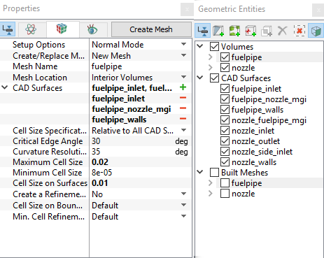
Fuel Pipe
|
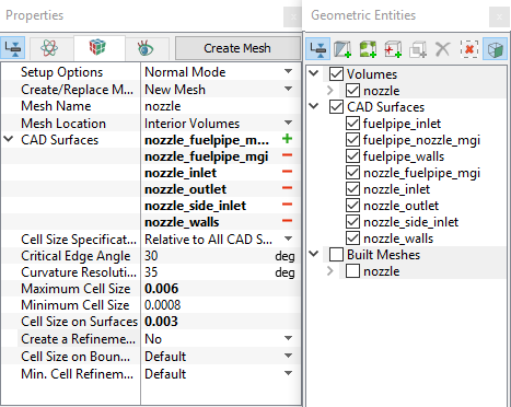
Figure 11.154 - Nozzle mesh settings |
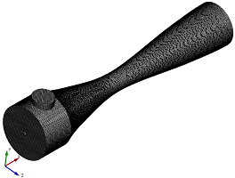
The mesh created for the fluid domain is shown below:
|
Figure 11.155 - Mesh |
Figure 11.156 - Cross-sectional view |

Create interfaces
In this section, the Mismatched Grid Interfaces (MGI) are generated between boundaries.
The steps to create the MGI is as follows:
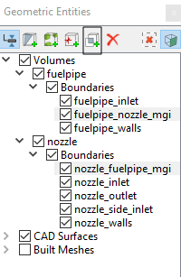
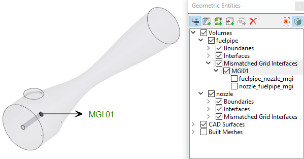
- In the Geometric Entities Panel > Volumes > Boundaries, select entities fuelpipe_nozzle_mgi and nozzle_fuelpipe_mgi shown under Boundaries (see, Figure 11.157).
- Click Connect Selected Boundaries via MGI
 icon to create the MGI entity MGI01 (see, Figure 11.158).
A group display of entities can be viewed using the Group Entities by Volumes/Types ![]() icon at Geometric Entities Panel toolbar.
icon at Geometric Entities Panel toolbar.
The new entities are created under MGI in Volumes (see, Figure 11.158).
|
Note: If MGIs are created by connecting the wrong boundaries, delete the created MGIs by clicking on Delete Selected Geometric Entity |