Defining Physics and Conditions
The physics and conditions are specified as follows.
Add Modules
- Click Select Modules in the Model Panel. The Physical Model Selection dialog box opens.
- Select Turbulence in the Available Modules list and click Add.
-
Select Multicomponent Mixing in the Available Modules list and click Add.
- Select Heat in the Available Modules list and click Add.
-
Click Close, to close the Physical Model Selection dialog box.
|
|
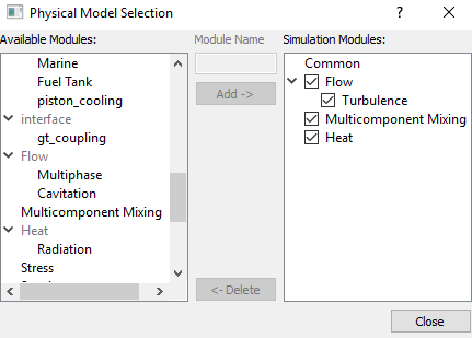
Figure 11.159 - Adding modules
|
Operating Parameters
Multicomponent Mixing
- Select Multicomponent Mixing in the Model Panel.
- Click three times Add Element
 icon for Components in the Model Tab of Properties Panel, to add components. icon for Components in the Model Tab of Properties Panel, to add components.
-
Rename comp_1, comp_2 and comp_3 as CH4, O2 and H2O respectively.
|
|
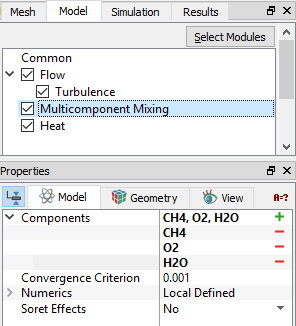
Figure 11.160 - Multicomponent parameters
|
Boundary Conditions
The boundary conditions are specified as follows:
Inlet
- Select inlet boundaries from the Boundaries list in the Geometric Entities Panel mentioned in the Table 11.7.
- Select Specified Volumetric Flux for Flow drop-down list in the Model Tab of Properties Panel.
- Enter Value under the Flow drop-down list for each boundary as given in Table 11.7.
- Enter Value for the Component CH4, Component O2 and Component H2O for each boundary respectively as given in Table 11.7.
- Select nozzle_inlet and set the Temperature to 350 K under Heat drop-down list as shown in Figure 11.162.
|
|
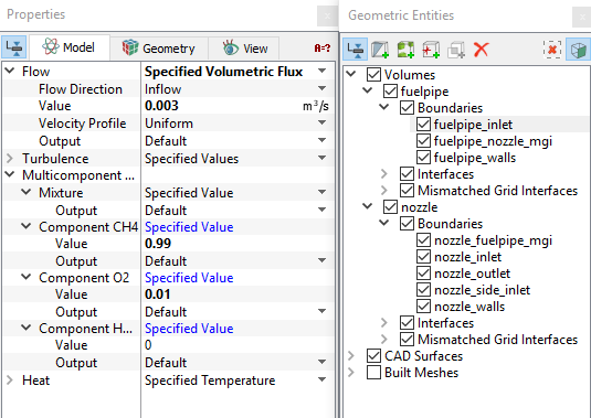
Figure 11.161 - Fuelpipe inlet
|
| Inlet boundary |
Inflow value |
CH4 (Component Value) |
O2 (Component Value) |
H2O (Component Value) |
| fuelpipe_inlet |
0.003 |
0.99 |
0.01 |
0 |
| nozzle_inlet |
0.007
|
0.01 |
0.99 |
0 |
| nozzle_side_inlet |
0.005 |
0 |
0.1 |
0.9 |
Table 11.7 - Components value
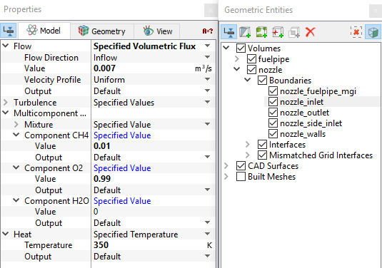
Figure 11.162 - Nozzle inlet
|
|
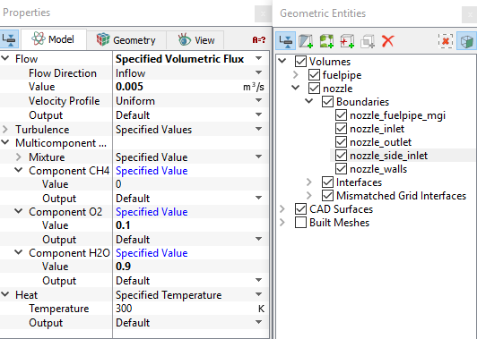
Figure 11.163 - Nozzle side inlet
|
Outlet
- Select nozzle_outlet from the Boundaries list in the Geometric Entities Panel.
- Select Specified Pressure Outlet for Flow drop-down list in the Model Tab of Properties Panel.
- Verify that the Pressure under the Flow is 101325 Pa.
- Enter 0.01 for Value in the Component CH4 list under Multicomponent Mixing drop-down list.
- Enter 0.9 for Value in the Component O2 list under Multicomponent Mixing drop-down list.
- Enter 0.09 for Value in the Component H2O list under Multicomponent Mixing drop-down list.
- For Component CH4, Component O2 and Component H2O expanded list:
- Set User Select for Output drop-down list.
- Set Yes for Average Concentration drop-down list.
|
|
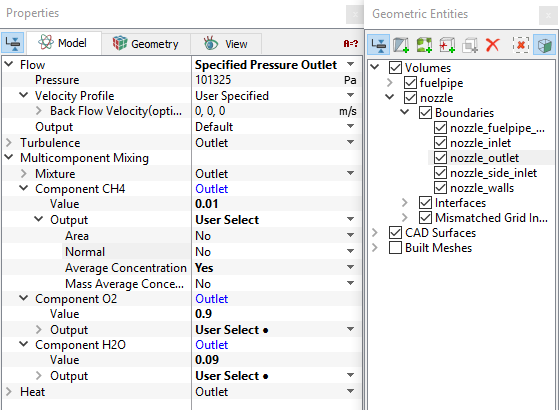
Figure 11.164 - Outlet conditions
|
Volume Properties
The multi-component mixing simulation requires to specify volume properties with respect to each module.
Common and Flow
- Select Volumes in the Geometric Entities Panel.
- Select Ideal Gas Law for Component CH4 list under Common drop-down list.
- For Component CH4 expanded list:
- Enter 10 Pa for Minimum Pressure
- Enter 16 kg/kmol for Molecular Weight
- For Component O2 expanded list:
- Enter 10 Pa for Minimum Pressure
- Enter 32 kg/kmol for Molecular Weight
- For Component H2O expanded list:
- Enter 10 Pa for Minimum Pressure
- Enter 18 kg/kmol for Molecular Weight
|
|
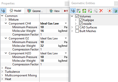
Figure 11.165 - Common and Flow properties
|
Multicomponent Mixing
- Select Volumes in the Geometric Entities Panel.
- Select Kinetic Theory from Viscosity drop-down list under Multicomponent Mixing > Mixture expanded list. See Figure 11.165.
- Specify the parameters for Output, Lennard-Jones Parameters and Initial Condition expanded list for each component as given in the Table 11.8:
| Component |
Output > Vol Avg Concentration |
Lennard-Jones Parameters |
Initial Condition |
| Diameter (angstrom) |
Energy (K)
|
Value |
| CH4 |
Yes |
3.758 |
148.6 |
0.01 |
| O2 |
Yes |
3.458 |
107.4 |
0.9 |
| H2O |
Yes |
2.605 |
572.4 |
0.09 |
Table 11.8 - Component parameters
Figure 11.166 - Multicomponent properties
