中文 English
You are here: Tutorials > Tank Filling > Setting up the model > Computational domain

Computational domain

This section explains the preparation of surfaces to create the domain. This is done with the operations splitting, combining and renaming of the surfaces.

Tank Filling Surfaces
  1. Select CAD Surfaces Tank_Filling in the Geometric Entities Panel.
  2. Select Split/Combine Geometry or Grid in the Mesh Panel.
  3. Select Split Disconnected from the Operation drop-down list in the Properties Panel, click Split Disconnected. Three new CAD Surfaces are created in the Geometric Entities Panel.
  4. Rename the CAD Surfaces Tank_Filling01 as Tank, Tank_Filling02 as Fuel_line and Tank_Filling03 as Nozzle.

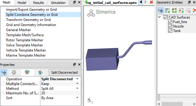
Figure 11.101 - Split of CAD surfaces


Fuel line Surfaces
  1. Select CAD Surfaces Fuel_line in the Geometric Entities Panel.
  2. Select Split by Angle from the Operation drop-down list in the Properties Panel.
  3. Enter 85 deg for Angle and 5 for Maximum No. of Splits, click Split by Angle. Six new CAD Surfaces are created in the Geometric Entities Panel.
  4. Select CAD Surfaces Fuel_line03 and Fuel_line04 and rename as Fuel_line_mgi_tank and Fuel_line_mgi_nozzle respectively.
  5. Select CAD Surfaces Fuel_line, Fuel_line01, Fuel_line02 and Fuel_line05.
  6. Select Combine from the Operation drop-down list in the Properties Panel, click Combine and rename as Fuel_line_wall.
 

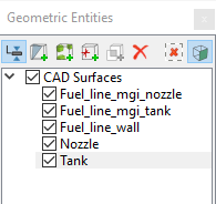
Figure 11.102 - Fuel line surfaces

Nozzle Surfaces
  1. Select CAD Surfaces Nozzle in the Geometric Entities Panel.
  2. Select Split by Angle from the Operation drop-down list in the Properties Panel.
  3. Enter 85 deg for Angle and 5 for Maximum No. of Splits, click Split by Angle. Five new CAD Surfaces are created in the Geometric Entities Panel.
  4. Select CAD Surfaces Nozzle_03 Nozzle_04 and Nozzle_05 and rename as Nozzle_air_out, Nozzle_mgi_fuel_line and Nozzle_fuel_in respectively.
  5. Select CAD Surfaces Nozzle_01, Nozzle_02. Select Combine from the Operation drop-down list in the Properties Panel, click Combine and rename as Nozzle_wall.
 

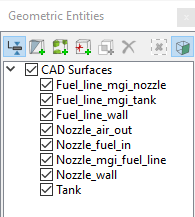
Figure 11.103 - Nozzle surfaces

Tank Surfaces
  1. Select CAD Surfaces Tank the Geometric Entities Panel.
  2. Select Split by Angle from the Operation drop-down list in the Properties Panel.
  3. Enter 85 deg for Angle and 10 for Maximum No. of Splits, click Split by Angle. Eleven new CAD Surfaces are created in the Geometric Entities Panel.
  4. Select CAD Surfaces Tank_07 and rename as Tank_mgi_fuel_line.
  5. Select CAD Surfaces Tank and select Split Disconnected from the Operation drop-down list in the Properties Panel.
  6. Click Split Disconnected. A new CAD SurfacesTank_11 is created. Rename Tank_11 as Tank_vent_out.
  7. Select remaining tank surfaces, select Combine from the Operation drop-down list. Click Combine and rename as Tank_wall.
 

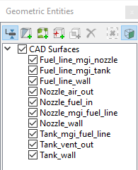
Figure 11.104 - Tank surfaces


Copyright © 2023 Simerics Inc.,