Building the Mesh
This section describes the step-by-step procedure for preparing the mesh for the tank filling model that contains tank, fuel line and nozzle. The mesh is used for creating the General Mesher.
Fuel line Mesh
- Select General Mesher in the Mesh Panel.
- Select CAD Surfaces Fuel_line_mgi_nozzle, Fuel_line_mgi_tank and Fuel_line_wall in the Geometric Entities Panel.
- Enter Maximum Cell Size as 0.004, Minimum Cell Size as 0.0003 and Cell Size on Surfaces as 0.002 in the Properties Panel.
- Click Create Mesh. A new mesh Fuel_line is created under Built Meshes in the Geometric Entities Panel.
- The meshed volume Fuel_line is generated under Volumes.
|
|
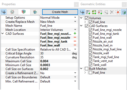
Figure 11.105 - Fuel line mesh settings
|
Nozzle
- Select General Mesher in the Mesh Panel.
- Select CAD Surfaces Nozzle_air_out, Nozzle_fuel_in, Nozzle_mgi_fuel_line and Nozzle_wall in the Geometric Entities Panel.
- Enter Maximum Cell Size as 0.004, Minimum Cell Size as 0.0003 and Cell Size on Surfaces as 0.002 in the Properties Panel.
- Click Create Mesh. A new mesh Nozzle is created under Built Meshes in the Geometric Entities Panel.
- The meshed volume Nozzle is generated under Volumes.
|
|
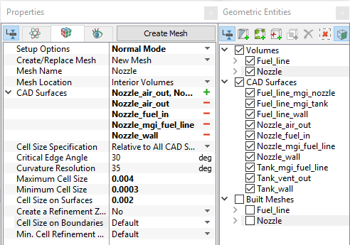
Figure 11.106 - Nozzle mesh settings
|
Tank Mesh
- Select General Mesher in the Mesh Panel.
- Select CAD Surfaces Tank_mgi_fuel_line, Tank_vent_out, and Tank_wall in the Geometric Entities Panel.
- Select Advanced Mode from the Setup Options drop-down list.
- Enter Maximum Cell Size as 0.008, Minimum Cell Size as 0.0003 and Cell Size on Surfaces as 0.004 in the Properties Panel.
- Select Cylindrical Zone under Create a Refinement Zone drop-down list
- Enter the parameter under the Refine Zone Options list as follows.
- Cell Size: 0.004
- Top Circle Center: 4.014, -2.615, 0.272 m
- Bottom Circle Center: 3.614, -2.614, 0.158 m
- Zone Radius: 0.03
Select Box Zone under Create a Refinement Zone drop-down list.
Enter the parameter under the Refine Zone 2 list as follows:
- Cell Size: 0.004
- First Corner: 3.616, -2.783, 0.158
- Diagonal Corner: 4.013, -2.445, 0.201
Click Create Mesh. A new mesh Tank is created under Built Meshes in the Geometric Entities Panel.
The meshed volume Tank is generated under Volumes.
|
|
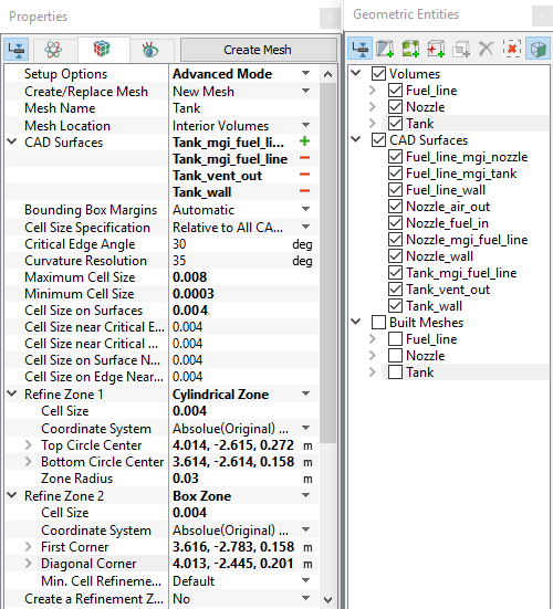
Figure 11.107 - Tank mesh settings
|
The mesh created for the fluid domain is shown below.
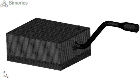
Figure 11.108 - Mesh
|
|
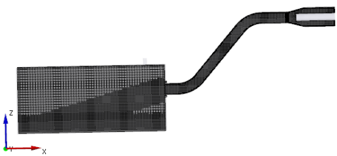
Figure 11.109 - Cross-sectional view
|
Create interfaces
In this section, the Mismatched Grid Interfaces (MGI) are generated between boundaries.
The steps to create the MGI is as follows:
- Geometric Entities Panel > Volumes > Boundaries, select entities shown under boundaries (see, Table 11.4).
- Click Connect Selected Boundaries via MGI
 icon to create the MGI entities (see, Figure 11.110).
A group display of entities can be viewed using the Group Entities by Volumes/Types  icon at Geometric Entities Panel toolbar.
| Fuel line and Nozzle |
Fuel_line_mgi_nozzle, Nozzle_mgi_fuel_line |
MGI01 |
| Fuel line and Tank |
Fuel_line_mgi_tank, Tank_mgi_fuel_line |
MGI02 |
Table 11.4 - Creating interfaces
The new entities are created under MGI in Volumes (see, Figure 11.111).
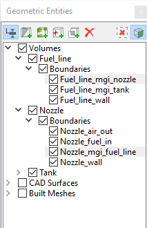
Figure 11.110 - Connecting fuel line and nozzle
|
|
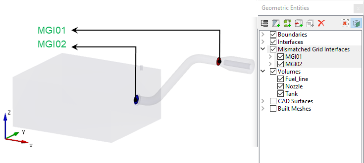
Figure 11.111 - Created interfaces
|
| |
Note: If MGIs are created by connecting the wrong boundaries, delete the created MGIs by clicking on Delete Selected Geometric Entity  icon and then recreate the MGIs. icon and then recreate the MGIs.
|