中文 English
You are here: Tutorials > Tank Filling > Setting up the model > Defining Physics and Conditions

Defining Physics and Conditions

The physics and conditions are specified as follows.

Add Modules
  1. Click Select Modules in the Model Panel. The Physical Model Selection dialog box opens.
  2. Select Multiphase in the Available Modules list and click Add.
  3. Click Close, to close the Physical Model Selection dialog box.


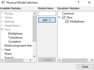
Figure 11.112 - Adding modules

Operating Parameters
Common
  1. Select Common in the Model Panel.
  2. Ensure Transient from the Time Definition drop-down list in the Model Tab of Properties Panel.
  3. Enter 40 for Number of Iterations.
  4. Enter Simulation Time (Duration) as 25 s and Number of Time Steps as 2500 for the Time Definition list.
  5. Enter 10 for Result Saving Frequency.
 

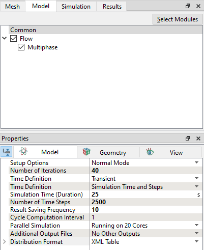
Figure 11.113 - Common operating parameters


Flow
  1. Select Flow in the Model Panel.
  2. Enter 0.1, 0.1 for Velocity and Pressure under Relaxation in Numerics list in the Model Tab of Properties Panel.
  3. Enter 0.3, 1 for Velocity and Pressure under Diagonal Relaxation.
  4. Select 2nd Order Upwind for Velocity under Numeric Scheme drop-down list.
  5. Enter 0.1 for Velocity and 0.01 for Pressure under Linear Solver Tolerance.
  6. Select Yes for Gravity Force drop-down list.
  7. Enter 0, 0, -9.81 m/s2 for in the Gravity Force list.


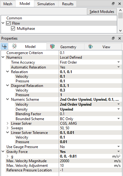
Figure 11.114 - Flow operating parameters
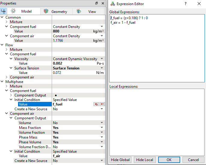
 

Multiphase
  1. Select Multiphase in the Model Panel.
  2. Click two time Add Element icon for Components in the Model Tab of Properties Panel, to add components.
  3. Rename comp_1 and comp_2 as fuel and air respectively.

  4. Enter 100 for the Compression Factor under Numeric Scheme list.
  5. Enter 30 for the Maximum Courant Number.
 

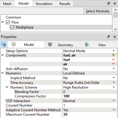
Figure 11.115 - Multiphase operating conditions
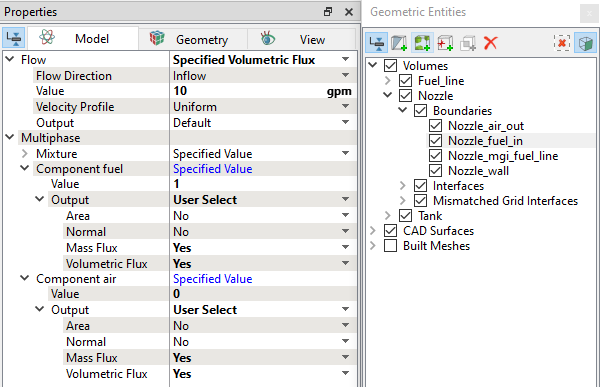
Boundary Conditions

The boundary conditions are specified as follows.

Inlet
  1. Select  Nozzle_fuel_in from the Boundaries list in the Geometric Entities Panel.
  2. Select Specified Volumetric Flux for Flow drop-down list in the Model Tab of Properties Panel.
  3. Enter 10 gpm for Value under the Flow drop-down list.
  4. Enter 1 for Value in the Component fuel list under Multiphase drop-down list.
  5. Verify that the Value in the Component air list under Multiphase is 0.
  6. Select User Select for Output drop-down list in Component fuel and Component air.
  7. Select Yes for Mass Flux and Volumetric Flux in Component fuel and Component air drop-down list.
 

Figure 11.116 - Inlet conditions


Outlet
  1. Select Nozzle_air_out and Tank_vent_out from the Boundaries list in the Geometric Entities Panel.
  2. Select Specified Pressure Outlet for Mixture under Flow drop-down list in the Model Tab of Properties Panel.
  3. Verify that the Pressure under the Flow is 101325 Pa.
  4. Enter 0 for Value in the Component fuel list under Multiphase drop-down list.
  5. Enter 1 for Value in the Component air list under Multiphase drop-down list.
  6. Select User Select for Output drop-down list in Component fuel and Component air.
  7. Select Yes for Mass Flux and Volumetric Flux in Component fuel and Component air drop-down list .
 

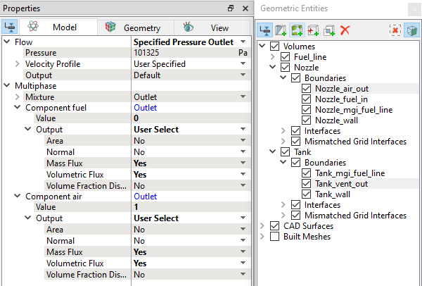
Figure 11.117 - Outlet conditions

Fluid Properties
  1. Select Volumes in the Geometric Entities Panel.
  2. Enter 800 kg/m3 for Value under Component fuel for the Common list in the Model Tab of Properties Panel.
  3. Enter 0.002 Pa-s for Value under Viscosity in Component fuel in the Flow list.

  4. Select Surface Tension under Surface Tension drop-down list in the Flow list.
Initial Conditions
  1. Click Edit Expressions icon in the Value under Initial Condition for Component fuel or Component air drop-down list, to open the Expression Editor dialog box.
  2. Enter the following for Global Expressions, (see Figure 11.118).
    f_fuel = (z<0.186) ? 1 : 0
    f_air = 1 - f_fuel
  3. Click OK, to close the Expression Editor dialog box.
  4. Enter f_fuel in the Value under Initial Condition in the Component fuel list.

  5. Enter f_air for the Value under Initial Condition in the Component air list.
  6. Select Yes for Mass Fraction, Volume Fraction, Phase Mass, and Phase Volume under Component Output list for the Component fuel and Component air list.
 

Figure 11.118 - Fluid properties


Copyright © 2023 Simerics Inc.,