Computational domain
This section explains the preparation of surfaces to create the domain. This is done with the operations splitting, combining and renaming of the surfaces.
Vortex Shedding
- Select Split/Combine Geometry or Grid in the Mesh Panel.
- Select CAD Surfaces vortex_shedding in the Geometric Entities Panel.
- Select Split by Angle from the Operation drop-down list in the Properties Panel.
- Enter 75 deg for Angle, click Split by Angle. Seven new CAD Surfaces are created in the Geometric Entities Panel.
- Rename the CAD Surfaces vortex_shedding_01,vortex_shedding_02, vortex_shedding_03, vortex_shedding_04, vortex_shedding_05, vortex_shedding_06, and vortex_shedding_07 as vortex_shedding_side1, vortex_shedding_side2, vortex_shedding_bot, vortex_shedding_top, vortex_shedding_inlet, vortex_shedding_outlet, and vortex_shedding_cylinder respectively .
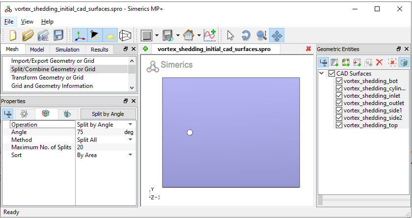
Figure 11.222 - Split of CAD surfaces
|
Note: Splitting of the surfaces can also be done by mouse selection using the Split by Mouse option from the Method drop-down list in the Geometry Tab of Properties Panel. |