Vortex Shedding
- Select General Mesher in the Mesh Panel.
- Select vortex_shedding_bot, vortex_shedding_cylinder, vortex_shedding_inlet, vortex_shedding_outlet, vortex_shedding_side1, vortex_shedding_side2 and vortex_shedding_top under CAD Surfaces in the Geometric Entities Panel.
- Click Add Surfaces
 of the CAD Surfaces in the Properties Panel. of the CAD Surfaces in the Properties Panel.
- Select Normal Mode under Setup Options and Absolute under Cell Size Specification.
- Enter Maximum Cell Size as 0.05, Minimum Cell Size as 0.001 and Cell Size on Surfaces as 0.05 .
-
Select Box Zone under Create a Refinement Zone drop-down list.
-
Enter the parameters under the Refine Zone Options list as follows:
- Diagonal Corner: 10, 1.5, 0.05 m
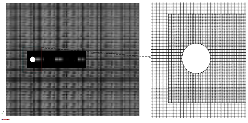
- Click Create Mesh. A new mesh vortex_shedding is created under Built Meshes in the Geometric Entities Panel.
- The meshed volume vortex_shedding is generated under Volumes.
|
|
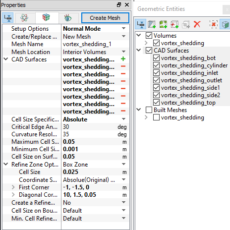
Figure 11.223 - Vortex Shedding mesh settings
|