中文 English
You are here: Tutorials > Vortex Shedding > Setting up the model > Defining Physics and Conditions

Defining Physics and Conditions

The physics and conditions are specified as follows.

Add Modules
  1. Click Select Modules in the Model Panel. The Physical Model Selection dialog box opens.
  2. Select Flow in the Available Modules list and click Add.
  3. Click Close to close the Physical Model Selection dialog box.
 

Figure 11.225 - Adding modules


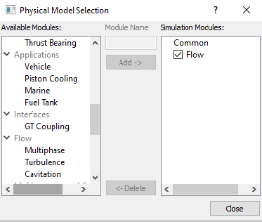
  Note: If the same physical module is being added multiple times into the Simulation Panel, it is mandatory to enter the name of the additional module. After giving the additional module name under Module Name, it will add as a suffix to the default name of the module .
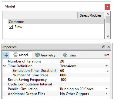
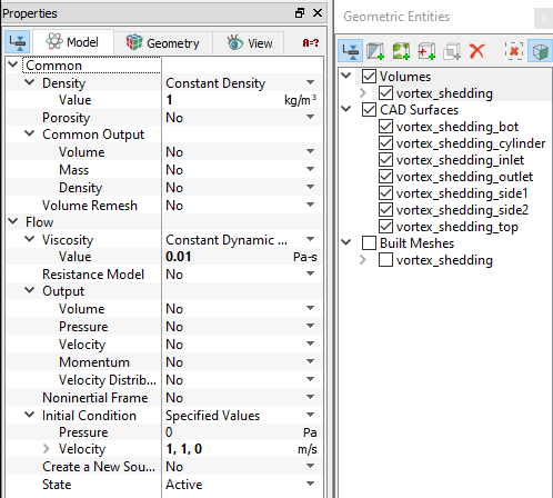
 

Operating Parameters
Common
  1. Select Common in the Model Panel.
  2. Select Transient from the Time Definition drop-down list in the Model Panel of Properties Panel.
  3. Enter 20 for Number of Iterations
  4. Enter Simulation Time (Duration) as 60 s and Number of Time Steps as 600.
  5. Enter 100 for Result Saving Frequency.


Figure 11.226 - Common operating parameters
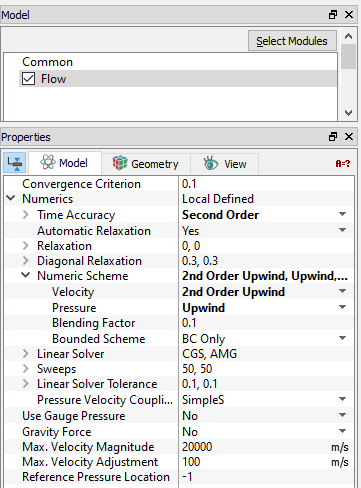
 

Flow
  1. Select Flow in the Model Panel.
  2. Select Second Order from the Time Accuracy drop-down list in the Model Panel of Properties Panel.
  3. Select 2nd Order Upwind for Velocity in the Numeric Scheme drop-down list.


Figure 11.227 - Common operating parameters


Fluid Properties
  1. Select the Volumes in the Geometric Entities Panel
  2. Enter 1 kg/m3 for Density under Density for the Common list in the Model Tab of Properties Panel.
  3. In the Flow > Viscosity drop-down list, verify that the Value is 0.01 Pa-s.
  4. Enter 1, 1, 0 m/s for Velocity under Initial Condition for the Flow.
 

Figure 11.228 - Properties for Air

Boundary conditions

The boundary conditions are specified as follows:
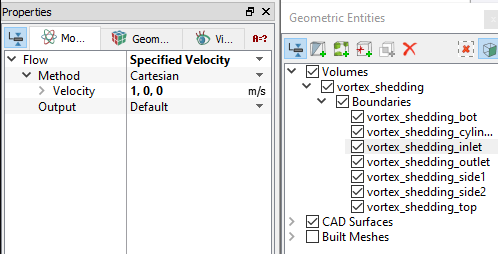
Inlet
  1. Select vortex_shedding_inlet from the Boundaries list in the Geometric Entities Panel.
  2. Select Specified Velocity from the Flow drop-down list in the Model Tab of Properties Panel.
  3. Enter 1, 0, 0 m/s for Velocity under Flow.
 

Figure 11.229 - Inlet conditions
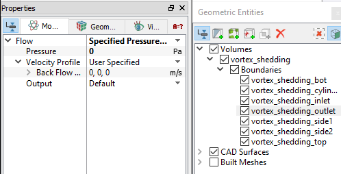
 

Outlet
  1. Select vortex_shedding_outlet from the Boundaries list in the Geometric Entities Panel.
  2. Select Specified Pressure Outlet from the Flow drop-down list in the Model Tab of Properties Panel.
  3. Enter 0 Pa for Pressure under Flow list.
 

Figure 11.230 - Outlet conditions
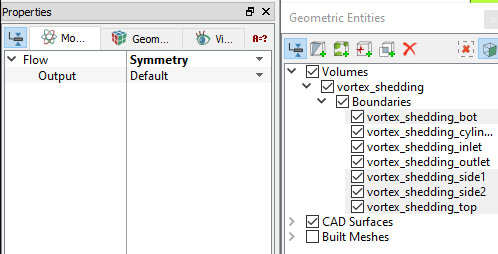
 

Symmetry boundaries

The conditions to the other boundaries are specified as follows:

  1. Select vortex_shedding_bot, vortex_shedding_side1, vortex_shedding_side2 and vortex_shedding_top from the Boundaries list under Volumes in the Geometric Entities Panel.
  2. Select Symmetry from the Flow drop-down list in the Model Tab of Properties Panel.
 

Figure 11.231 - Symmetry boundary conditions


Copyright © 2023 Simerics Inc.,