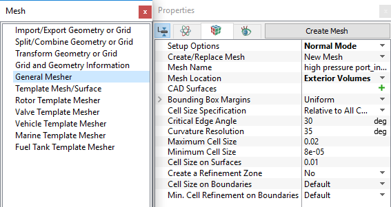
4.2.2 General Mesher
General Mesher is used to generate a volume mesh in any arbitrary geometry using the Binary Tree Mesher technique. It can be used to generate meshes inside and outside very detailed and complex arbitrary shapes.
The General Mesher is accessed as follows:
Mesh Panel > General Mesher.
The parameters for General Mesher are available in the Properties Panel.

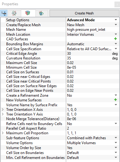
Figure 4.16 - General mesher
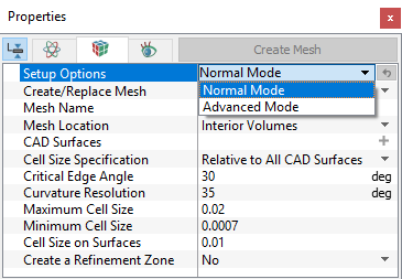
Setup OptionsThe two modes under Setup Options are: |
Figure 4.17 - Setup options |
|
Note: The user is free to switch between Advanced Mode and Normal Mode as needed. Switching back to Normal Mode does not reset the more complex settings, but rather keeps them in effect. |
A) Normal Mode Options
|
The Normal Mode contains the following settings: |
Figure 4.19 - Normal mode options |
For brief description of each method, click the respective Method or click description below.
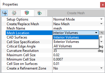
Interior Volumes
This creates meshes in the interior of all volumes as defined by the closed CAD Surfaces. The selection of CAD Surfaces must be such that the volume is “water tight.” If not, the exterior volume mesh will “leak” inside and no interior volume will be created.
- The General Mesher first creates all volumes and then deletes any unwanted volume. Because it first creates all volumes (interior and exterior), the presence of neighboring volumes has an influence on the interior mesh of each other. If a “cleaner” mesh is desired, it is recommended to mesh each interior volume independently.
- The bounding box influences the size of the mesh formed in interior volumes. In this regard, meshing multiple volumes or changing the bounding box options will result in different meshes.
-
In some cases, the relative position of the bounding box influences the resolution of the mesh formed in interior volumes. In some cases, an unwanted fine resolution of a boundary can be corrected by a slight displacement of the bounding box.
|
Note: Ensure that the interior volumes are “water tight.” |
Exterior Volumes
This creates meshes on the exterior of all volumes as defined by selected closed CAD Surfaces.
- The extent of an exterior volume will depend on the limits set under the bounding box options. The outer surfaces of this bounding box will be meshed as boundaries.
- An external volume can be used to create a virtual “wind tunnel” around an object
|
Note: The General Mesher first creates all volumes and then deletes any interiors volume. |
All Volumes
This creates meshes on both the interiors and exterior of all volumes as defined by the selected CAD Surfaces.
- Internal CAD Surfaces will be meshed as Interfaces.
- The extent of the exterior volume will depend on the limit set under the bounding box options. The outer surfaces of this bounding box will be meshed as boundaries.
-
Interior volumes, as defined by selection of CAD Surfaces , must be “water tight.” If not, the external volume mesh will “leak” inside and no interior volume will be formed.
|
Note: Only CAD Surfaces and associated Volumes that are selected in the Geometric Entities Panel will be meshed. |
|
Figure 4.21 - Interior volumes |

Figure 4.22 - Exterior volumes |
Figure 4.23 - All volumes |


|
Note: The bounding box influences the distribution of the mesh formed in interior volumes. In this regard, meshing multiple volumes or changing the bounding box options will result in different meshes. In some cases, an unwanted fine resolution of a boundary can be corrected by a slight displacement of the bounding box. |
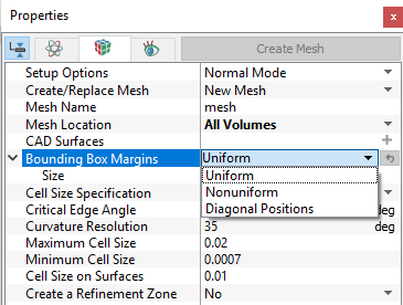
Uniform Margins: The bounding box will be constructed using uniform margins. When it is selected, it requires to set the Size as a sub-parameter.
|
Figure 4.26 - Uniform-Relative size (0.5) |
Figure 4.27 - Uniform-Absolute size (0.5) |


|
Note: If the Cell Size Specification is Absolute Size, the thickness of all margins will be equal to the input value of Size in meters. |
|
|
Note: If the Cell Size Specification is Relative Size, the thickness of the margins will be equal to the input value of size times the dimension of the object in each direction. |
Nonuniform Margins:
The bounding box is constructed using non-uniform margins. When selected, it requires setting the Minimum Side Sizes and Maximum Side Sizes as a sub-parameter.
Diagonal Positions:
The bounding box is constructed using two points defining opposite corners of the box. When selected, it requires setting the Minimum Corner Position and Maximum Corner Position as a sub-parameter.
- If the Cell Size Specification is Relative Size, the location of the two corner points will off-set from the maximum and minimum of the object being modelled, such that the default of Minimum Corner Position = (0,0,0) and Maximum Corner Position = (1,1,1) results in a tightly wrapped bounding box, as shown in Figure 4.28.
- An example of Relative Size, using non-default settings of Minimum Corner Position = (-1,-1,-1) and Maximum Corner Position = (2,2,2) is shown in Figure 4.29. Note how the minimum and maximum corner values times the object’s <length, height, width> are added to the minimum corner of the object to get the max or min bounding box corners. In this case, the result is a box centered around the object. Also note that the reference lengths are different for each direction, based on the unequal
 dimensions of the cylinder.
|
Figure 4.28 - Minimum corner position = (0,0,0) and Maximum corner position = (1,1,1) |
Figure 4.29 - Minimum corner position = (-1,-1,-1) and Maximum corner position = (2,2,2) |


Cell Size Specification
|
Figure 4.30 - Cell size specification |
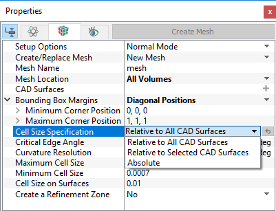

Figure 4.31 - Relative cell size specification
Absolute Size
This means all coordinates and lengths (meters) to the model’s coordinate system.
Relative Size
This is used to specify the meshing parameters requiring length, such as the Bounding Box Margins, Maximum Cell Size, Minimum Cell Size, and Cell Size on Surfaces as a relative size to the CAD Surfaces.
Critical Edge Angle
This controls the accuracy with which the CAD Surfaces edge is resolved by the mesh.
- Smaller the edge angles, higher the resolution.
|
Figure 4.32 - Critical edge angle |
Figure 4.33 - Critical edge angle (30° and 20°) |


Curvature Resolution
This controls the accuracy with which the CAD Surfaces edge is resolved by the Mesh.
- Smaller the angles, higher the resolution.

Figure 4.34 - Curvature resolution angle |

Figure 4.35 - Curvature resolution default (35°) and user defined (20°) |

Figure 4.36 - Curvature resolution (Boundary) default (35°) and user defined (20°) |
Maximum Cell Size
This controls the size of the cells throughout a mesh volume. Maximum Cell Size is a length scale specified in terms of Relative Size or Absolute Size.
- No cell in the volume can have a cell size larger than the Maximum Cell Size.
- This is applied throughout the Volume being meshed. For additional refinement inside a volume, the Create a Refinement Zone option can be used.
|
Figure 4.37 - Maximum cell size |

|

Minimum Cell Size
This limits how small cells can be in attempting to resolve the geometry using the general mesher. Minimum Cell Size is a length scale specified in terms of Relative Size or Absolute Size. It applies to all the cells in a volume (see, Figure 4.38).
- Smaller values provide higher resolution. If the general mesher hits the limit set by the Minimum Cell Size, then sub-features are formed. A small value of Minimum Cell Size is normally recommended to allow the general mesher, the flexibility to resolve fine features and prevent the formation of sub-features.
- Minimum Cell Size is a lower limit and will not be required if the general mesher is able to meet the resolution criteria ; Curvature Resolution and Critical Edge Angle using larger cells. (i.e. the cells may not be as small as the Minimum Cell Size).
- Large values of Minimum Cell Size is also used to “plug” holes in a “dirty” geometry, but at expense of the creation of sub-features and the possible loss of resolution in other areas.
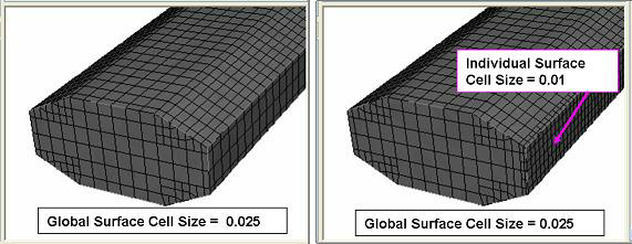
Cell Size on Surfaces
This controls the size of the cells for all surfaces of a mesh volume. Cell Size on Surfaces is a length scale specified in terms of Relative Size or Absolute Size. No cell on the surface can have a cell size larger than the Cell Size on Surfaces.
- This parameter is applied for all the surfaces of the volume being meshed.
- Smaller values will provide higher resolution.
-
Usually the Cell Size on Surfaces is specified smaller than the maximum cell size to capture the geometric features with higher resolution.

Figure 4.39 - Refined setting |

Figure 4.40 - Coarse setting |
This controls the size of the mesh cells within defined zones of a volume. Any number of refinement zones can be created. Three types of zones are available: Cylindrical Zone Refinement, Box Zone Refinement and User Defined Refinement.
Cylindrical Zone Refinement and Box Zone Refinement
- Cells within a zone are subsequently based on Cell Size, which is similar in function to Maximum Cell Size.
-
Once a refinement zone is created, the desired dimensions of the zone geometry and the Cell Size is set prior to the General Mesher operation. An example of two refinement zones (Box and Cylinder) is shown in Figure 4.41.
The specified value of Cell Size is applied inside the meshed zone.

Figure 4.41 - Example of refinement zones (Box and Cylinder)
User Defined Refinement
This option is used, when user wants to refine any arbitrary region in the domain. User need to write a expression to define a particular region and cell setting to be used.
-
An example of user defined refinement setting is shown in Figure 4.42. Here, rzone is the function used to refine the mesh in the triangular region.
-
The value of 0.01 m Cell Size setting is applied inside the refinement zone, elsewhere 0.04 m is used.
- Mesh created using expression is shown in Figure 4.43.

|
|

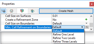
Min. Cell Refinement on Boundaries
This limits how small the cells can be in attempting to resolve a CAD geometry using the General Mesher. It controls the limiting size of the boundary cells generated next to an individual CAD Surface. Unlike, Minimum Cell Size, which is used to control the smallest cells in the entire volume, the Minimum Cell Refinement on Boundaries is used to provide local refinement on CAD Surfaces that present small features such as tight gaps, sharp curvature etc.
|
The Min. Cell Refinement on Boundaries is specified for a selected CAD Surface prior to the General Mesher. The operation as follows: Mesh Panel > General Mesher Geometric Entities Panel > CAD Surface > [Desired Surface] Properties Panel > Geometry Tab > Min. Cell Refinement on Boundaries > [User Input]
Three different levels of limiting are offered under Min. Cell Refinement on Boundaries: Refine One Level, Refine Two Levels and Refine Three Levels.
|
Figure 4.45 - Min. cell refinement on boundaries-options |
B) Advanced Mode Options
|
The Advanced Mode options available are: |
Figure 4.46 - Advanced mode options |
For brief description of each parameters, click the respective Method or click Description drop-down list below.
Cell Size near Critical Edges
This controls the size of the cells near a critical edge. It is a length scale specified in terms of Relative Size or Absolute Size. No interior cell adjacent to a critical edge can have a cell side larger than the specified value of the Cell Size near Critical Edges.
- Smaller values will provide higher resolution.
- Cell Size near Critical Edges is applied for all critical edges of the volume being meshed.
- A critical edge is one that subtends an angle more acute than the Critical Edge Angle.

|
|

Cell Size near Critical Points
This controls the size of the interior cells near critical points. Cell Size near Critical Points is a length scale specified in terms of Relative Size or Absolute Size. No interior cell near a critical point can have a cell size larger than the Cell Size near Critical Points (see, Figure 4.48).
- Cell Size near Critical Points is applied for all critical points of the volume being meshed.
- Smaller values will provide higher resolution.
- A critical point is the point connecting two or more critical edges.
Cell Size on Surface Near Edges
This controls the size of the boundary cells near the critical edge. It is a length scale specified in terms of Relative Size or Absolute Size.
- No boundary cells adjacent to a critical edge can have a cell side larger than the Cell Size on Surface Near Edges (see, Figure 4.47).
- Cell Size on Surface Near Edges is applied for all critical edges of the volume being meshed.
- Smaller values will provide higher resolution.
- Cell Size on Surface Near Edges is similar to Cell Size near Critical Edges, but the first applies to boundary cells and the second applies to interior cells.
Cell Size on Edge Near Points
This controls the size of the cells on edges near a critical points. It is a length scale specified in terms of Relative Size or Absolute Size.
- No Edge adjacent to a critical point can have a cell size larger than the Cell Size on Edge Near Points (see, Figure 4.48).
- Cell Size on Edge Near Points is applied for all critical points of the volume being meshed.
- Smaller values will provide higher resolution.
Volume Name by Surface Prefix
This allows to activate naming of volumes based on the prefix of the CAD Surface names. In conjugate heat transfer analysis, CAD domain may contains multiple solid components and a fluid volume, in such cases Volume Name by Surface Prefix is helpful.
For example, if a mesh is generated with the CAD Surfaces: inlet_inlet, inlet_walls, inlet_mgi, volute_mgi, volute_outlet and volute_walls, the Volumes are automatically generated as inlet and volute.
Tree Orientation X-AxisThis gives the orientation of the bounding box used in the Binary Tree Mesh algorithm. The user provides the
|
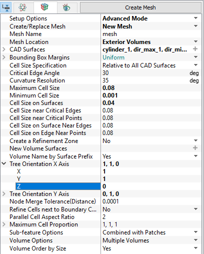
Figure 4.51 - Tree orientation settings |
 ,
,  and
and  components of a vector that will become the new orientation of the X-Axis of the

Tree Orientation Y-Axis
This gives the orientation of the bounding box used in the Binary Tree Mesh algorithm. The user provides the  ,
,  and
and  components of a vector that will become the new orientation of the Y-axis (see, Figure 4.50) of the bounding box.
Node Merge Tolerance (Distance)
This sets the tolerance at which two nodes would be merged into a single point. Node Merge Tolerance is a length scale specified in terms of Relative Size or Absolute Size.
- Smaller values will provide higher resolution.
- Node Merge Tolerance (Distance) is applied for all critical points of the volume being meshed.

Figure 4.52 - Critical points merged |
|

Refine Cells next to Boundary Cells
This refines the cells in the transition from one boundary to the next such that they are of the same order in size.
- This is applied for all critical points of the volume being meshed (see, Figure 4.53).
- This is a length scale specified in terms of Relative Size or Absolute Size.
Parallel Cell Aspect Ratio
This controls the aspect ratio of the cells created by the Binary Tree Mesher. Parallel Cell Aspect Ratio controls mesh density near the control volume surfaces and has a value between 1 and 8.

Figure 4.54 - Aspect ratio = 4 |
|

Maximum Cell Proportion
This limits the aspect ratio of the cells generated by the General Mesher. The aspect ratio of cells can be controlled in  ,
,  and
and  direction. The default value for
  is 1,1,1 respectively. The aspect ratio can be relaxed in a particular direction depending on the geometry and flow physics. For e.g., in the case of a long pipe with smaller diameter, the aspect ratio can be relaxed to 2,1,1 in order to reduce the cell count.
Sub-feature Options
|
A sub-feature is a “stair-step” mesh created, when the Simerics Binary-Tree Mesh algorithm is unable to resolve a feature of the geometry. The Sub-feature Options are used to control the grouping of sub-features. The sub-features are grouped together as follows:
To the extent that a sub-feature is a small deviation in the precision of the mesh it will have only a minor effect on accuracy of the solution. They can be combined with the appropriate adjacent boundary.
|
Figure 4.56 - Sub-features options |
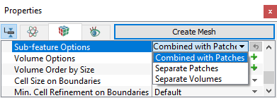

Figure 4.57 - Sub-features
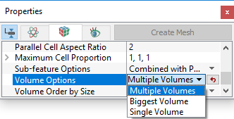
Volume Order By Size
This allows ordering of Volumes in the Geometric Entities Panel based on the cell count (bigger volume to smaller).