4.3 Interface Creation
Interface
This is an internal boundary within a model. It can reside within a volume or connect two separate volumes. It connects the mesh cells on either side of the interface.
There are two types of Interfaces:
-
Internal Interface: This interface is automatically created by the software during mesh generation when there are cells on either side of a CAD Surface. Internal interfaces can be created in one of two ways:
-
When an isolated CAD Surface is present inside an enclosed volume. For example, a plate inside a cube.
-
When the CAD Surfaces defining an enclosed volume are present inside another bigger volume. For example, a sphere inside a cube. The General Mesher will create two volumes with the surface of the sphere being an internal interface between the two volumes.
-
-
Mismatched Grid Interfaces ( MGI): This option is used to connect two disconnected Volumes to allow flow to pass between them.
|
Figure 4.96 - Create MGI |
Figure 4.97 - MGI |
MGI (Mismatched Grid Interface)
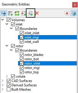
The procedure for creating an interface is as follows:
- Geometric Entities Panel > [Desired Boundaries]
- Geometric Entities Panel > [ Connect Selected Boundaries via MGI]
 .
.
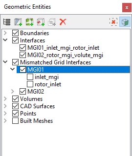
Once created, MGI sets are listed in the Geometric Entities Panel, under the heading MGI (e.g. MGI 01). The boundaries included in an MGI set are listed under the respective set, as shown for MGI01 in Figure 4.98

Interface Connection MethodsWhen a connection is made using a MGI, the following parameters are specified for a selected MGI set in the Model Tab of Properties Panel. |
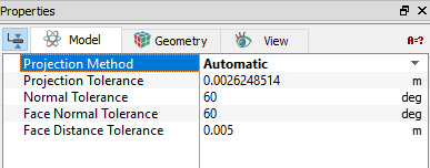
Figure 4.99 - MGI connection |
Projection Method
This controls the type of projection surface used for connecting boundaries under the MGI option.

Figure 4.100 - Projection method
The three options for the Projection Method are Automatic, Planar and Cylindrical.
Automatic
This selects the projection surface used for connecting boundaries under the MGI option automatically.
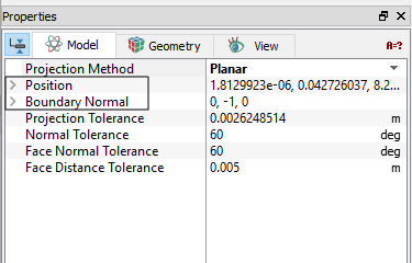
PlanarThis uses a plane as the projection surface for connecting boundaries under the MGI option.
|
CylindricalThis uses a cylinder as the projection surface for connecting boundaries under the MGI option.
|
Figure 4.102 - Cylindrical projection |
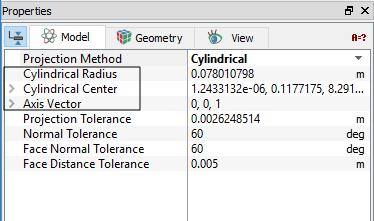
Projection Tolerance
The maximum distance between the local boundary face and the projection surface. To connect via MGI, the two boundaries should be closer than the projection tolerance. Any boundary faces farther from the projection surface than this tolerance, will not be connected via MGI.

Figure 4.103 - Projection tolerance |

Figure 4.104 - Normal tolerance |
Normal Tolerance
The angle between two boundaries has to be less than the Normal Tolerance for them to be connected via MGI.
Face Distance Tolerance
The distance between any two individual cell faces of two boundaries has to be less than the Face Distance Tolerance for them to be connected via MGI.
|
Figure 4.105 - Face distance tolerance |

Figure 4.106 - Face normal tolerance |

Face Normal Tolerance
The angle between the Normal of any two individual cell faces of opposing boundaries has to be less than the Face Normal Tolerance for them to be connected via MGI.
|
Note: The projection surface dictated by the Projection Method is only used for mapping the boundaries. It does not necessarily have to lie between the boundaries to create the connection. |
Guidelines for creating MGIs
- Inspect the list of geometric entities to see if the desired interface has been created. Click Interface to see if it has the desired shape. (What is displayed is what “exists”).
- If the desired interface is not created, click MGI set and try a different Projection Method, Normal Tolerance, and/ or Projection Tolerance.
- If the desired interface is still not created, it may be that Sub-features or other irregularities have been included in the boundaries to be connected and are preventing a connection due to the Normal Tolerance. It may be that the Sub-features should be grouped with an adjacent wall or other boundary.
- If the desired interface is still not created, it may be necessary to create a better physical correlation between the boundaries to be connected. This may require regeneration of the CAD Surfaces.
- If a connection is made, i.e. if interfaces are generated, they are listed in the Geometric Entities Panel, under the heading Interfaces.
- A boundary can only be selected for inclusion in one MGI set. (For this reason, all boundaries potentially involved in an Interface should be included in the same MGI set at the time of creation.)
- A MGI may or may not generate an interface.
- The boundaries and interfaces associated with a MGI set may be indicated by toggling its check-box and observing the check-boxes under the Boundaries and Interface list.
- Additional boundaries may be added to a MGI set by dragging and dropping using Left Mouse Button.
|
Note: For more information, see the section on MGI and/or Interfaces. |