Contours
The steps to create contours are:
- Click the Load Results option in the Simulation Panel.
- Select the required result file in the ensuing Load Results dialog box, click Open.
Surface elevation
An interesting contour for the planing hull is the surface elevation behind the hull in the wave region. The following steps are used to create this:
- Click Create an Isosurface
 icon in the Geometric Entities Panel. An Isosurface 01 is created under Derived Surfaces.
 - Select Volume Fraction [Component water] under Variables for the Isosurface Variable drop-down list in the Geometry Tab of Properties Panel.
- Select Above Value for the Option drop-down list and enter 0.5 for the Value.
- Select hull under CAD Surfaces in the Geometric Entities Panel .
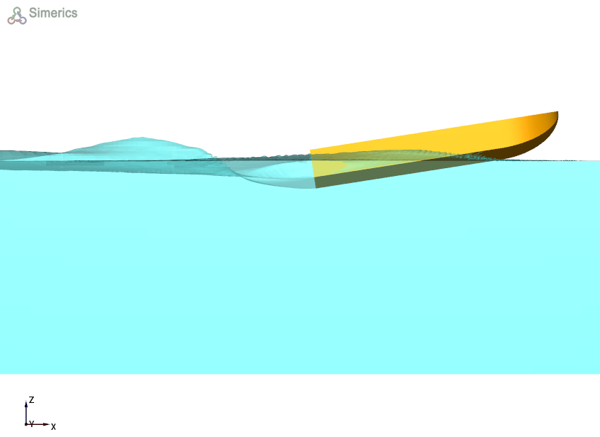
Figure 8.56 - Planing hull over an isosurface with volume fraction > 0.5
Surface distribution variable
The distribution of dynamic pressure on the hull surface can be represented for the planing hull as follows:
- Select hull under Boundaries in the Geometric Entities Panel .
- Select Dynamic Pressure under Derived Variables for the Variable drop-down list in the Results Panel.
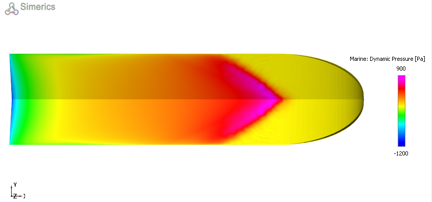
Figure 8.57 - Dynamic pressure distribution on the hull surface