


All icons become active when you select a variable from the Variable list. Alternatively, you can right-click a variable in the list to see the same options. Each icon and its function is described in the following table.
|
Icon |
Description |
|---|---|
|
|
New opens the New Variable dialog box where you can enter a name. |
|
|
Edit displays the selected Variable in the Expression and/or Units box where you can edit it. |
|
|
Copy makes a duplicate of the selected variable and opens the New Variable dialog box where you can enter a name for the copy. |
|
|
Delete removes the selected variable from the list. |
|
|
Set all Variables to use Hybrid Values sets all variables to use hybrid values. |
|
|
Set all Variables to use Conservative Values sets all variables to use conservative values. |
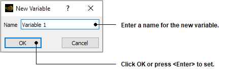
When you click New
![]() to create a new variable, the New Variable
dialog box is displayed.
to create a new variable, the New Variable
dialog box is displayed.
There are a few guidelines to follow when selecting a variable name.
You cannot create a variable with the same name as an object.
You cannot create a variable with the same name as an expression. For example, if you have an expression named
Radius, you must choose a different variable name for that expression.Within the Ansys CFX Expression Language some variables are known by short names to save typing in the full variable name. For example,
prefers toPressure. Although it is possible to create a variable with the same name as an abbreviated variable, it is ignored. For example, if you use a variable with the namepin an expression, it returns the valuePressurein all cases, no matter what the definition of the variable is.
Click Edit
![]() to edit both the fundamental and user variables. Select the
expression used to define the variable from a list of existing expressions for
user variables. The expressions available from this list are those which you
have created in the expression editor. For details, see Expressions Command.
to edit both the fundamental and user variables. Select the
expression used to define the variable from a list of existing expressions for
user variables. The expressions available from this list are those which you
have created in the expression editor. For details, see Expressions Command.
For fundamental variables, the units are changeable. Click the drop-down arrow  next to the Units box to see the available units for the
selected variable. This means, for example, that you could create a legend which
uses alternative angle units (such as degrees or radians) by clicking the drop-down arrow and selecting new units.
next to the Units box to see the available units for the
selected variable. This means, for example, that you could create a legend which
uses alternative angle units (such as degrees or radians) by clicking the drop-down arrow and selecting new units.
Note: These settings override the global units setting, defined in the Edit Menu. For details, see Options Command.
The variable type used affects all quantitative calculations and plots in Ansys TurboGrid.
This is useful only for advanced postprocessing and is not relevant for Ansys TurboGrid. It is included to maintain consistency with other Ansys CFX products. Refer to the CFD-Post documentation for more information on the differences between hybrid and conservative variable values.
In this example, an isosurface that has a fixed radial distance from the X axis is created using the expression defined in the Expression Editor Example.
Select Tools > Variables from the main menu to open the variable editor.
Click New
 to create a new variable. When the New
Variable dialog box appears enter the name
to create a new variable. When the New
Variable dialog box appears enter the name
Radial Distanceand click .In the variable editor, use the Expression drop-down list to select the expression
radialwhich you created earlier. Click Apply to create the new variable.
This variable now appears in the list of available variables and can be used like any other variable. Notice that the variable type is listed as User.
You can now create an isosurface using this variable. For details on creating isosurfaces, see Isosurface Command.
Select Insert > User Defined > Isosurface from the main menu, enter a name, then click on the New Isosurface dialog box.
In the Geometry tab for the isosurface, set Variable to
Radial Distance.Set Value to
20m. This is a suitable value for the Rotor 37 geometry used in Tutorial 1. You may need to alter this value to something more sensible depending on the geometry you are viewing.Click the Color tab and set Mode to
Variable.Select a sensible variable (for example,
Maximum Face AngleorAxial Distance) with which to color the isosurface.Set Range to
Localso that the full color range is used on the isosurface.Click Apply to create the isosurface object.
You should now see the isosurface in the viewer. All points on the isosurface are a distance of 20 m (or whatever value you used in the Value box) from the X-axis.