Design Mode
There are two different options to define hub and shroud contours.
|
Direct design of the two contours |
|
Design of center line; |
Hub, Shroud
In the first case, hub and shroud can be designed separately.
Middle
In the second case, only the geometric center line of the flow channel will be modified. The contours result from specifying a relative cross section distribution. It may either be linear or could be loaded from a file using the Progression dialog.
The first value of each line is the relative meridional coordinate x along the center line, with x=0 at the inlet cross-section and x=1 at the outlet cross-section. The second value is the relative cross section Arel, which allows to compute the related absolute value:
The cross section is used to determine the meridional width b vertical to the flow direction.
This strategy is mainly suitable for mixed-flow impellers, it's suboptimal for centrifugal impellers with relative sharp direction change from axial to radial.
Axial dimensions
The axial reference position as well as the axial extension of the meridional shape can be specified in the Axial dimensions area on the right.
The reference point ![]() can be located at center line start point or end point. All connector points □ define their axial position relative to this point.
can be located at center line start point or end point. All connector points □ define their axial position relative to this point.
The reference point specifies the axial start or end position of the meridional contour. When changing the axial position of the reference point, the complete meridional geometry is shifted accordingly. The opposite center line point defines the axial extension.
Both values can also be modified interactively in the graphics:
•axial start/ end position by first/ last point of center line
•axial extension by last/ first point of center line
Inlet/ outlet lines
Inlet and outlet lines have a special context menu to define the tilt mode, either as axial distance between hub and shroud point or angle of the line.
The EDIT context menu item allows the specification of an exact value.
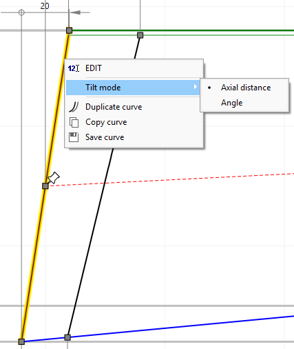
The following limitations with regard to inlet/ outlet lines exist:
•axial distance option is not available for the outlet of centrifugal pumps, fans, compressors and inlet of radial inflow gas turbines because the outlet (inlet) width b2 (b1) is already fixed by the main dimensions.
•axial distance and angle option are not available for the inlet of Francis turbines because the horizontal inlet width b1z as well as the inlet diameters at hub dH1 and shroud dS1 are already fixed by the main dimensions.
Curve types
Hub/ shroud contours can consist of several curves, which are highlighted on mouse-over.
The initially generated contour can be split using the "Split curve" context menu item. Neighboring curves can be merged using the "Merge curve" context menu item of the connector between the curves.
Each curve can have one of the following types selectable by context menu:
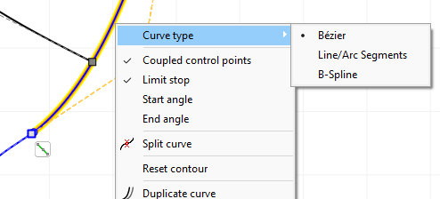
•Bezier
The curve is defined by the position of the Bezier points.
¢ Details
•Line/Arc Segments
The curve consists of two straight line connected by a circular arc.
¢ Details
•B-Spline
The curve consists of piecewise composed polynomials of a certain degree.
¢ Details
These marker types exist for the curves:
|
reference point at start/ end point of center line |
□ |
connector point at start/ end point of each curve (active point) |
○ |
inner control point of a curve (active point) |
ê |
point of max. curvature of the contour (information only) |
A tangential connection between curves can be switched on or off using the icon beside the connection point:
|
tangential connection |
|
non-tangential connection |
The manipulation of the contours can be achieved by shifting the positions of the control points. As an alternative, the position of control points can be realized by input of numerical values by right click on it (see Graphical dialogs). Trailing edge can be rotated by moving its control points at hub or shroud. Inclination angle of trailing edge can be numerically determined by clicking the right mouse button on one of these control points.
In the design process for the meridional contours, the user should try to create curvatures which are as steady as possible in order to minimize local decelerations. The maximum values of the curvature should be as low as possible and should entirely disappear at the end of the contours. These requirements are met very well by Bezier curves. Local cross section 2πrb should grow from inlet to outlet as uniformly as possible.