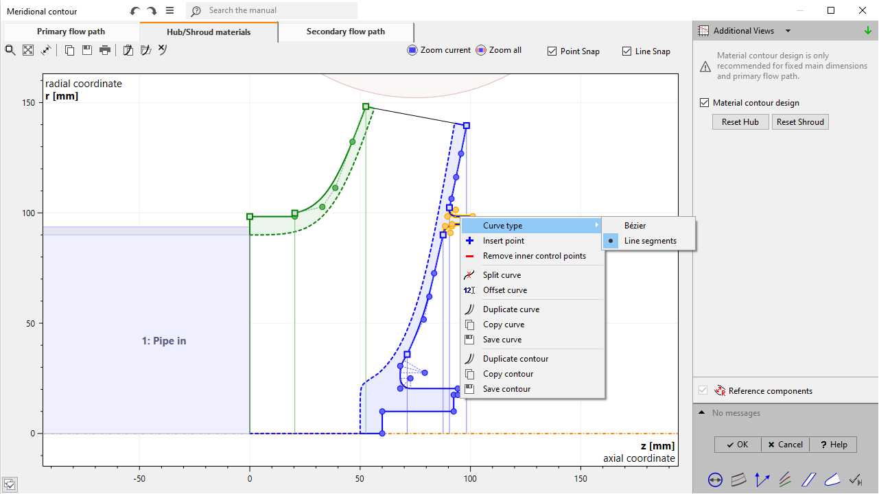
Meridional material solids can be designed by selecting the "Hub/Shroud materials" page on top left and activate the feature on the right side. Initial contours will be visible, which can be manipulated using the control points and the context menu of the curve.
After the model finishing the meridional material parts and the blade solid are connected to a single solid geometry, "Material domain".
Material design
Hub & Shroud materials can be designed by manipulating their meridional contours.
The shroud material design is available only for shrouded impellers.
|
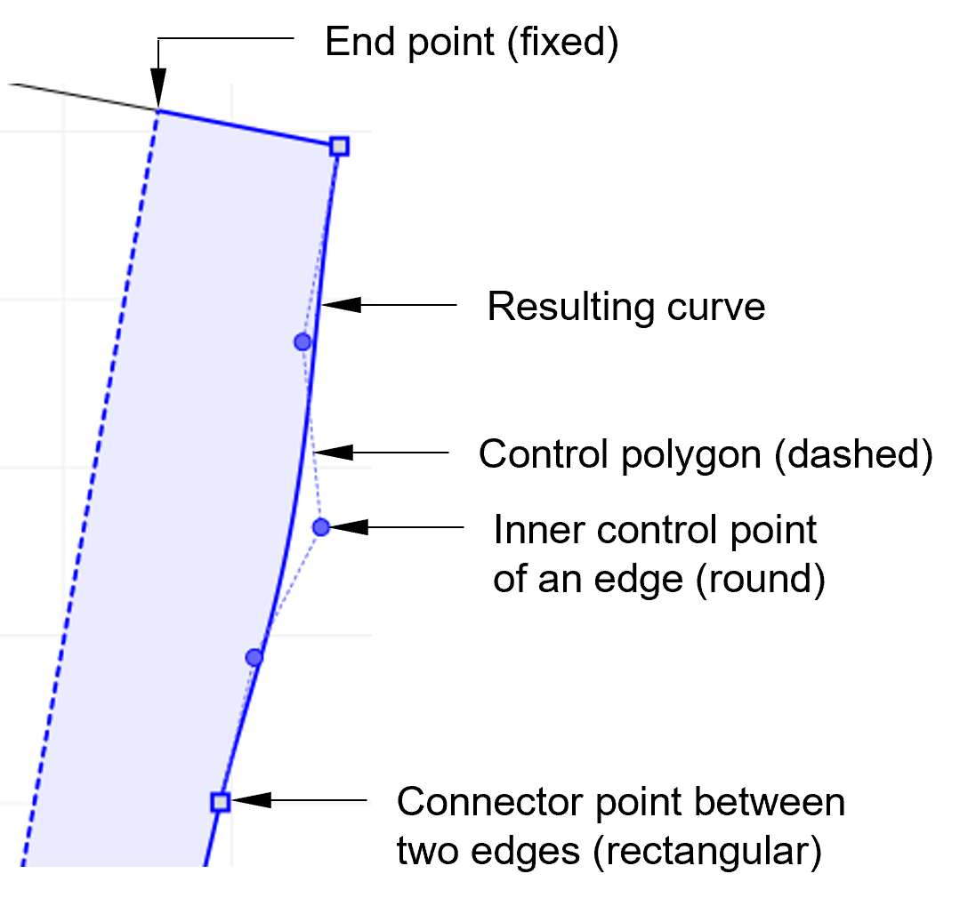
By activating the "Material contour design" a default contour is generated. This contour is represented by a wire connecting the endpoints of meridional hub or shroud contour and can be modified interactively using its graphical elements. To provide complex contours the wire can consist of various edges which can be configured independently from each other. They are separated visually by squared control points. In contrast circular control points belong to edges and are connected by a dashed control polygon. Apart from the endpoints of the wire, all control points are moveable. |
Context menus of contour wire
Besides drag & drop of control points context menus of graphical objects are alternative means to modify the contour. They are accessible via right-clicking and contain useful tools for the graphical object underneath.
|
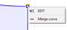
Connector point•EDIT: Opens a small panel to set coordinates of connector point. •Merge curve: Transforms connector into inner control point by merging control polygons. |
|
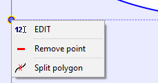
Inner control point•EDIT: Opens a small panel to set coordinates of inner control point. •Remove point: Remove the selected inner control point. •Split polygon: Transform inner control point into connector point. The result are two control polygons of the original type. |
|
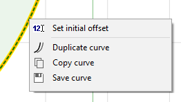
Meridional contour of primary flow path•Set initial offset: Resets the complete wire using a user-defined offset. |
|
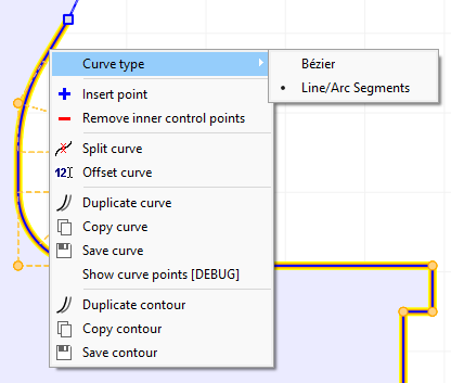
Edge types of contour wireAn edge of a contour wire can be one of the following types: •Bezier curve •Line/Arc Segments curve |
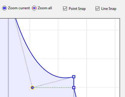
Snapping
To simplify contour design snapping of points on coordinates and lines can be used. This mode can be chosen by selecting one of the snapping types at top right of the diagram:
|
Snapping types•Point: Currently moved point snaps to x and/or y coordinate of other points. •Line: Currently moved point snaps to lines defined by all pairs of points.
The currently used snapping property is illustrated by a red dotted line while moving a point. Note that snapping can be deactivated temporarily by pressing the Crtl key while dragging. |